Eng-Tips is the largest engineering community on the Internet

Intelligent Work Forums for Engineering Professionals

  • Congratulations waross on being selected by the Eng-Tips community for having the most helpful posts in the forums last week. Way to Go!

Unsymmetric Section Neural Axis Vs Principal Axes Maximum and Minimum Stresses

Status
Not open for further replies.

Kristina Sornikova

Aerospace
Nov 8, 2016
87
US
Dear All,

Sorry for this basic question. I learn in past Mc/I only applicable to principal axes.
But this professor use neutral axis, which is at angle to principal axes to find max and min point, but use principal axes for stress?
Here is link:

So my question: If use neutral axis, I get same point for one end 'B'.
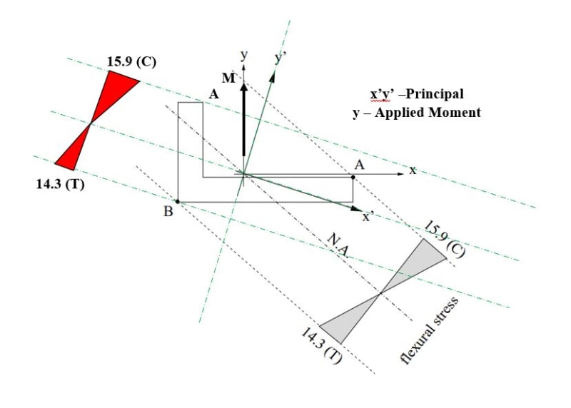
But if use principal, I get different point for 'A'? Which is correct? See image below.
When you do section bending + axial (assume shear zero) check of any unsymmetric section, you use principal or neutral for extreme fiber and bending stress?
I know neutral means no axial stress, and principal means no Ixy, meaning no twisting if applied moment is not aligned with principal.
I also not getting same stress distribution (where is tension where is compression) if use principal compared to neutral using Mc/I.
May be I am doing wrong. See image below, bit confusing. What you think?
Capture_ctcake.jpg
 
Replies continue below

Recommended for you

You can calculate principal axes ok, good. So for each axis there's an I and a y for each corner of the angle.

then resolve the applied moment into these two axes, and sum the resulting stresses.

Lick O'paint.

"Hoffen wir mal, dass alles gut geht !"
General Paulus, Nov 1942, outside Stalingrad after the launch of Operation Uranus.
 
How you calculate extreme fiber points for bending check?
You use neutral axis or principal axis?
The professor use neutral axis for points but transformed using angle of principal axis.
That is my confusion.
 
I would use the principal axes to define the points.

(sarcastically) what is this "neutral axes" you speak of ? that is different to a principal axes ?

The centroid is the centroid, a point determined by geometry. I'd've thought that for your angle the principal axis would go through the mid point of each leg of the angle; and the other principal axes would be perpendicular, through the centroid (and this may, will?, pass through the corner of the angle.)

The elastic neutral axis is a line of zero bending stress, clearly there are two different "neutral axes" each coincident with a principal axis.

"Hoffen wir mal, dass alles gut geht !"
General Paulus, Nov 1942, outside Stalingrad after the launch of Operation Uranus.
 
I agree with principal for both points and stress, I, y etc.
But then I see the paper by the professor, he has neutral axis by equal of axial stress=0.
Then he find angle from principal axis of this neutral axis.
That is why I confuse, why neutral axis? Both neutral and principal pass through centroid, yes.
What importance in stress analysis of complex section under complex loading of neutral axis?

His paper again for ref:
 
it appears, after a quick look, that the paper is doing interaction of the moments about the two principal axes of the section to get the maximum moment on the section, sort of like Mohr's circle for in-plane loading. The maximum moment is not necessarily aligned with the section's principal axes.

in other words, the max and min principal bending moments do not occur along the cross sections "principal axes".

 
moments don't necassarily occur on principal directions, but the applied moment can be resolved into the principal axes.

"Hoffen wir mal, dass alles gut geht !"
General Paulus, Nov 1942, outside Stalingrad after the launch of Operation Uranus.
 
A good approach is the use of the equation that incorporates Ix, Iy and Ixy, about the section centroid and a conveniently placed coordinate system. The fibre distances and moments are in the same system.
 
Greg,
Yes never go college, this all self taught from eng-tips.com, :) just joking.
So I still have no good reply on what the importance of neutral axis for unsymmetric section bending check as the professor did?
Mohr's circle is sure really nice way.
 
the neutral axis is just the line perpendicular to the line of maximum bending moment.
 
I wouldn't "fuss" about the NA.

A unsymmetric (and also symmetric) section bends (at least theoretically) about the principal axes, which I understand you know how to calculate.
The "straight forward" analysis I learnt is to apply the moment in components along the principal axes, and then simply My/I in two directions and sum. Getting back to your sketch, the NA should be normal to moment, the minor principal axis will go through the mid-point of each leg of the angle ... that's just a short-cut ... work it out for yourself (maybe it is self apparent). The major principal axis is normal to this, through the centroid (and also the corner of the angle (maybe, probably, sounds reasonable).

Now maybe having done it that way (summed two principal components) you can look at the moment applied and the resulting NA (normal to the moment vector) which will give you the "y" term but the I ? well like greg posted that's Mohr's circle for section inertia, you want I at some angle to the principal direction.

Clear as mud ?

"Hoffen wir mal, dass alles gut geht !"
General Paulus, Nov 1942, outside Stalingrad after the launch of Operation Uranus.
 
Yes very muddy.
I have no problem principal method, all good with me.

Only problem is the neutral axis 'fuss', :).
The professor neutral axis is calculate from equate maximum axial stress (from principal M component and MOI) to zero.
He find angle with principal of 24.5 deg, it is not perpendicular to vertical applied moment?
He also find extreme points from neutral axis, not principal axis.
 
ok, so he's calculating the entire stress field due to bending about both axes, and figuring where the stresses sum to zero ? and calling that the neutral axis, ok

so you'd have two plots of stress along the two arms of the angle, both linear, both (maybe) changing sign ... no, the "major" axes (with the larger I) I think the axis is through the centroid and the corner of the angle ... so one leg have tension stress decreasing to zero, and the other leg has compression stress. yes?

but why ? I've read your post (again) ... his NA is inclined to the principal axes, dependent on the loading. It seems you have to work through the principal axis bending to determine this NA ... it seems like a lot of work ... is it just to check the principal axis solution ? But ... if I'm right, the applied moment is applied as components along the principal axes; and from this one component will produce tension stress in one leg but the other component will produce tension and compression, so the sum will be either ...
1) addition tension on the far end and compression (summed with zero) at the corner, or
2) tension + compression at the far end and tension (summed with zero) at the corner.

It's not obvious that these cross zero (ok, 1) will be 2) could be tension at both ends). but in 2) the other leg should cross from tension to compression so you'll have a point of zero stress. It's not obvious that the stress in the two legs will be linear with respect to some line through this zero point ... which I think is required if you calculate stress for "y" from this line ??

Looking at your sketch, I think the principal axis should pass through the corner of the angle. I know it's just a sketch, but try to draw it correctly (and bad sketch can mislead).

"Hoffen wir mal, dass alles gut geht !"
General Paulus, Nov 1942, outside Stalingrad after the launch of Operation Uranus.
 
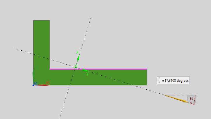
I make part with same dimensions, measure inertia in NX and make this display, NX show principal axes same as professor has to scale and correct angle.
You can see 'x' is major principal, 'y' is minor principal.
Capture_byvfkg.jpg
 
Yes, and the critical point of maximum stress under combined bending moments is not along the dashed line axes, rather it is at the point at the maximum distance from the centroid.
 
yes, calculate the stress from both moment components at the 6 corner points, and sum for the critical stress.

and from these you should be able to find points of zero stress

"Hoffen wir mal, dass alles gut geht !"
General Paulus, Nov 1942, outside Stalingrad after the launch of Operation Uranus.
 
Yes:
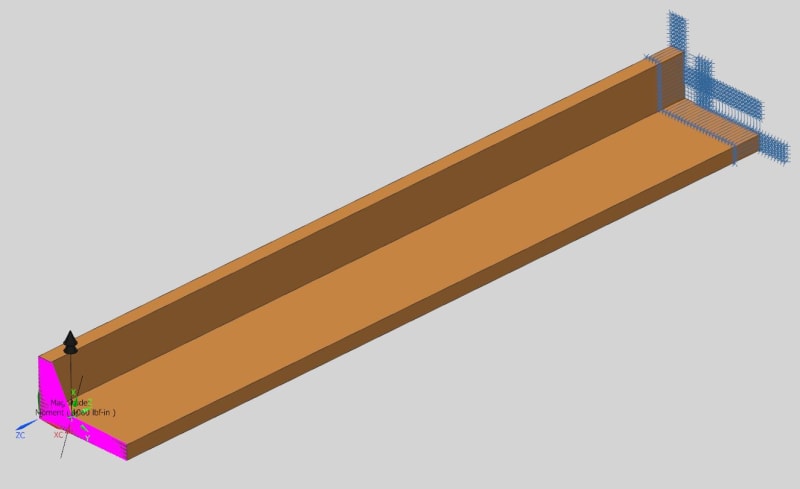
Model: All hex elements, model long enough so far field value correct in midspan.
1000 in-lb vertical on RBE3 dependent node, RBE3 is CG point to face. Other end pinned.
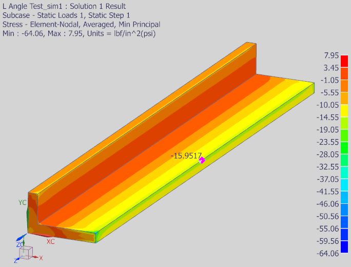
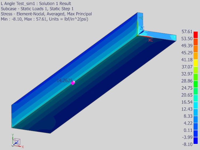
Min and max principal stress results show professor is correct, neutral axis will tell correct points of max and min stress.
Capture2_zfhjt9.jpg

Capture1_bqj8st.jpg
Capture_mdd1tv.jpg
 
silly me, I thought you'd hand calc it ...

not clear why the stress is constant along the span ? Isn't the load vertical ? bending along the span ??

"Hoffen wir mal, dass alles gut geht !"
General Paulus, Nov 1942, outside Stalingrad after the launch of Operation Uranus.
 
Just got out my old uni book. Let z and y be the horizontal and vertical axis respectively (+ve y down, +ve z right side). If Iyz=0, then fx = Mz.y/Iz + My.z/Iy (x into paper). If a moment M is applied at an angle a then -My = M.sin(a) and Mz = M.cos(a). Substituting the two component moments into fx and setting fx=0, then rearranging gives y/z = Iz.tan(a)/Iy = tan(b). The angle b is the inclination of the neutral axis relative to the horizontal axis, being a principal axis. The neutral axis defines the stress plane. Hope that helps!
 
Status
Not open for further replies.

Part and Inventory Search

Sponsor

Back
Top