Eng-Tips is the largest engineering community on the Internet

Intelligent Work Forums for Engineering Professionals

  • Congratulations waross on being selected by the Eng-Tips community for having the most helpful posts in the forums last week. Way to Go!

Unsymmetric Section Neural Axis Vs Principal Axes Maximum and Minimum Stresses

Status
Not open for further replies.

Kristina Sornikova

Aerospace
Nov 8, 2016
87
US
Dear All,

Sorry for this basic question. I learn in past Mc/I only applicable to principal axes.
But this professor use neutral axis, which is at angle to principal axes to find max and min point, but use principal axes for stress?
Here is link:

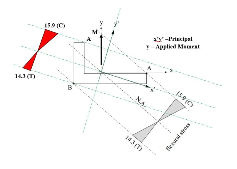
So my question: If use neutral axis, I get same point for one end 'B'.
But if use principal, I get different point for 'A'? Which is correct? See image below.
When you do section bending + axial (assume shear zero) check of any unsymmetric section, you use principal or neutral for extreme fiber and bending stress?
I know neutral means no axial stress, and principal means no Ixy, meaning no twisting if applied moment is not aligned with principal.
I also not getting same stress distribution (where is tension where is compression) if use principal compared to neutral using Mc/I.
May be I am doing wrong. See image below, bit confusing. What you think?
Capture_ctcake.jpg
 
Replies continue below

Recommended for you

rb, the load is not a force, its a moment at the end. I could hand calc, but wanted to see FEM too.
 
"If Iyz=0" = if the section is symmetric. Here Ixy is finite, so we have principal axes (inclined to the geometry x- and y- axes).

KS ... ok, a cantilever with a moment.
But you've already hand calc'd the stresses from the principal axes, right? So from those stress you can deduce the NA, then transform the applied moment into this axis, and the "y" from this axis (seems really confusing and circular).

Your sketch is further confusing 'cause it shows stresses at different location (the principal axis method says peak stress on the standing leg, the NA analysis says the horizontal leg. Maybe this is for "clarification" ? But if both methods are right then they should give the same results. The principal axis method is certainly correct (if calc'd properly !) IDU this "NA "method, other than as a check ... there's no way to determine when there is zero stress without doing the principal axis analysis (which solves the problem so why do more ?). You know I[sub]NA[/sub] from your principal axis derivation (at some angle to Imax). If I were teaching this, I'd compare the principal axis stresses with those from using Ixx.

How does the angle FEM deflect ?

"Hoffen wir mal, dass alles gut geht !"
General Paulus, Nov 1942, outside Stalingrad after the launch of Operation Uranus.
 
Yeah, is why I put in red, I not sure if it was correct, extreme points was confusing.
But now I think I know, point A on upper leg using principal axis system will not be highest stress compressive, only point A on horizontal leg using NA will be, is it better?
Both method will not be correct for the same points.
Neutral gives you the correct points, principal gives stress at those points.
If you use principal for points, you will get wrong A.
In this case top leg corner, and wrong max compressive stress, which is at other point A on horizontal leg.
Yeah?
 
The professor may just be showing you one method that works for this type of section, to add to your collection of methods and giving you another way to solve for the design stresses. Much of engineering involves looking at a problem and finding the easy way to solve it. What he or she is showing you is not "the" way but "a" way to look at this problem.
 
I've never heard of this NA approach before, and you can't get there with the principal axis solution first.

"Both method will not be correct for the same points." ... then one approach is "wrong" (and I know the principal axis method is "right").

"But now I think I know, point A on upper leg using principal axis system will not be highest stress compressive, only point A on horizontal leg using NA will be, is it better?" ... I'm not so sure ... I think the most you can say is the critical stress will be at one of the obvious three locations (the ends of the two legs and the corner) ... so calc all three to find out. In "My/I" all three terms vary so I think it is difficult to say this will be lower than that.

"Neutral gives you the correct points, principal gives stress at those points." ... yeah, but that's a lot of work (finding the NA) compared with just calcing the three corners.

"If you use principal for points, you will get wrong A." ... IDTS ... the most is that the principal axes method makes you calc some non-critical points. Also remember you're looking simply at stress, what about allowables ? the compression allowable at the corner is much higher than the compression allowable at the end of the leg (vulnerable to crippling).


"Hoffen wir mal, dass alles gut geht !"
General Paulus, Nov 1942, outside Stalingrad after the launch of Operation Uranus.
 
You know rb, you are right, using principal is not wrong, its just more points to calculate. But what if the section is more complex, many more corners?
 
It would be interesting to see how the non symmetrical bending equation compares to FE.
fz = [(Iyy.Mx + Ixy.My).y - (Ixy.Mx + Ixx.My).x] / (Ixx.Iyy - Ixy^2)
Choose an appropriate coordinate system. How close are the results?
 
that would (should) be the same same the principal axis method ... you're using the components of the principal moment of inertia instead of the principal MoI themselves. But it would be a check on the principal axes results.

Yes a more complex section would be more points to calc (or maybe careful selection of a set of points). But how do you calc the NA without doing it ? Do you say the bending stress about principal axis (1) is the -ve of the stress about the other (2) ... M1x/I1 = -M2y/I2 ? ok, that would give you an equation of a line ... but ...
1) you'd calc I[sub]NA[/sub] from the angle to the principal axis, and
2) how do you determine M[sub]NA[/sub] ? the applied moment is "unlikely" to be normal to this NA (since the slope of the NA is dependent on geometry terms, not just loads) ...

oh, but you've said the NA only helps you identify the critical points to calculate bending stress.

ok, but bending stress is only 1/2 of MS ... the thing you really need to calculate. It could be that the corner which has the higher allowable has the lower bending stress (and so a higher MS) but the longer of the two legs will have the lower crippling allowable (and it's MS may, or may not, be lower than the shorter leg).

"Hoffen wir mal, dass alles gut geht !"
General Paulus, Nov 1942, outside Stalingrad after the launch of Operation Uranus.
 
All good points. NA would be easy, you know loads and moments, you know principal axes (only one set, max and min), then you use max axial stress = 0 formula, specially for complex section, yes?

Agree on cripple, I think this post was for mainly max and min principal.
Min principal may not at critical crippling location. That is separate check yeah?
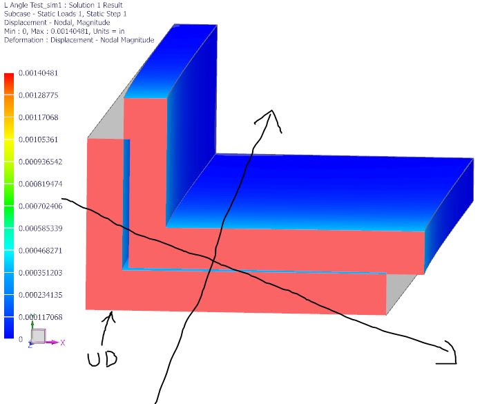
See below deformed plot with undeformed marked in black at midspan, why is no aligning with principal axes? In fact its turning counter clockwise?

Capture3_xb9f1n.jpg
 
I've used the example given in the original post link in a template I put together many years back (template was personal interest only). It carries out a hand calculation of the L section. The N/A (not N/A, should have said zero stress axis) and the principals are shown in a diagram on the last page, with results. Note that the two angles in the example equate to the single in the attachment. I hope the applied hand analysis method helps.
 
 https://files.engineering.com/getfile.aspx?folder=4fd0b1ab-26dd-46f5-b79e-fe0e69476b9e&file=L_Section_Example.pdf
what does "Neutral Axis" mean if there is bi-axial bending ?

In the principal axes approach the applied moment is resolved into components along the principal axes, and two bending stress calcs are summed for the complete story. The will be some line (actually I think think it will be several piecewise linear line segments) of zero stress (between the positive tension and negative compression) but ...


"Hoffen wir mal, dass alles gut geht !"
General Paulus, Nov 1942, outside Stalingrad after the launch of Operation Uranus.
 
If it is a timoshenko beam in pure bending the neutral axis will be straight, and stresses away from it will increase by their perpendicular distance from it only, and there will be no net axial force.

Cheers

Greg Locock


New here? Try reading these, they might help FAQ731-376
 
yes, that's our analysis for a beam with bending about one axis ... and would be applicable if the applied moment was on one principal axis.

but going back to the OP's pict ... it suggests that the principal axes method doesn't get the right result ... which is IMHO wrong.

we've talked about how to infer the critical point. A suggestion has been that determining the NA allowas to you figure which corner is furthest from the NA (the RH A, near the x axis) and so this'll have the highest stress. But you can look at the applied moment ... the larger component will be weak axis bending (min principal axis) ... larger component load, smaller MoI ... then LH A will have a higher compression than RH A. But LH A will see tension from the strong axis bending (max principal axis) ... smaller load, larger MoI ... probably smaller stresses. A bunch of offsetting minors ... IDK.

You still haven't explained this NA analysis method ... can you show the calcs ?

"Hoffen wir mal, dass alles gut geht !"
General Paulus, Nov 1942, outside Stalingrad after the launch of Operation Uranus.
 
rb, my pic was just what I thought it should be as I use principal method, compared to what professor had, so it was no correct.
We know now NA method only gives two extreme point for max and min principal stress, like you said other points with one edge free leg may be more critical for cripple.
I have no NA method, NA only show correct points just for min and max stress, yea?

But I still not sure why section turning counter clockwise, away from principal? End fixity in the FEM causing it maybe?
 
ok, OP is a "cartoon", NP.

I don't think there is a straight line NA in this case. From the principal axis analysis, there will be two lines of zero stress ... 1 for each principal axis. As before stress1 = M1*y/I1, and stress2 = M2*x/I2 ... humm, that suggests a line (!?) ... y/x = -M2/M1*I1/I2.

I still think this is all a "red herring" ... calculating the stresses at several points isn't a pain, well not That much of a pain, and is probably necessary to calculate MS at "all" points ... "all" means enough to capture the critical point.

It would be interesting to compare principal axes stresses with bending stresses from the geometrical axes (horizontal and vertical) ... ie M*y/Ixx

"Hoffen wir mal, dass alles gut geht !"
General Paulus, Nov 1942, outside Stalingrad after the launch of Operation Uranus.
 
Just for info, the example section calc given in the original post link used the principal axis approach. Using the non-symmetric equation approach (Ixx, Iyy, Ixy components) gave the same stresses. The fun begins when you have peak shear and torsion stress points about the profile, when loaded under additional direct forces and torsion! You have additional points to consider and you need to calculate all stress components!
 
good points. A section loaded only in bending is not particularly real ... sure it can happen, but typically it is transverse shear that causes the bending.

thinking about the rotation ... if I was this angle, I'd twist to align the strong axis with the load ... in this case so the bending moment is normal to the strong axis. I think that should minimize the strain energy.

"Hoffen wir mal, dass alles gut geht !"
General Paulus, Nov 1942, outside Stalingrad after the launch of Operation Uranus.
 
Umm, but in this case, strong axis (y') rotates to be in line with moment axis, not perpendicular?
Do anyone have a generalized spreadsheet that can do any generalized section and any loading?
So I can define any section with X,Y points and loading in the spread sheet, spreadsheet do all calculation including tension and shear interaction?
 
Status
Not open for further replies.

Part and Inventory Search

Sponsor

Back
Top