Continue to Site

Eng-Tips is the largest engineering community on the Internet

Intelligent Work Forums for Engineering Professionals

  • Congratulations GregLocock on being selected by the Eng-Tips community for having the most helpful posts in the forums last week. Way to Go!

Unusual soldier pile and lagging scheme

Status
Not open for further replies.

bridgebuster

Active member
Jun 27, 1999
3,969
I need an opinion on a contractor’s proposed soldier pile and lagging scheme, see sketch. He’s rebuilding a bridge abutment in stages and can’t drive sheeting. The abutment isn’t very tall and sits on a mat foundation. The sheeting would have to go through the mat.

Toward the rear of the work area he wants to drive piles a few feet in and hold them with braces that would be wedged against the wingwall – I’m OK with the concept. However, near the front of the abutment he wants to drive two soldiers two feet below his demolition line and rely on two walers acting as cantilever beams to hold the piles in place.

In theory I see his point but I’m not convinced. I was thinking of stacking some mafia blocks on the "cantilever". It will interfere a bit with the formwork but they should be able to work around it.
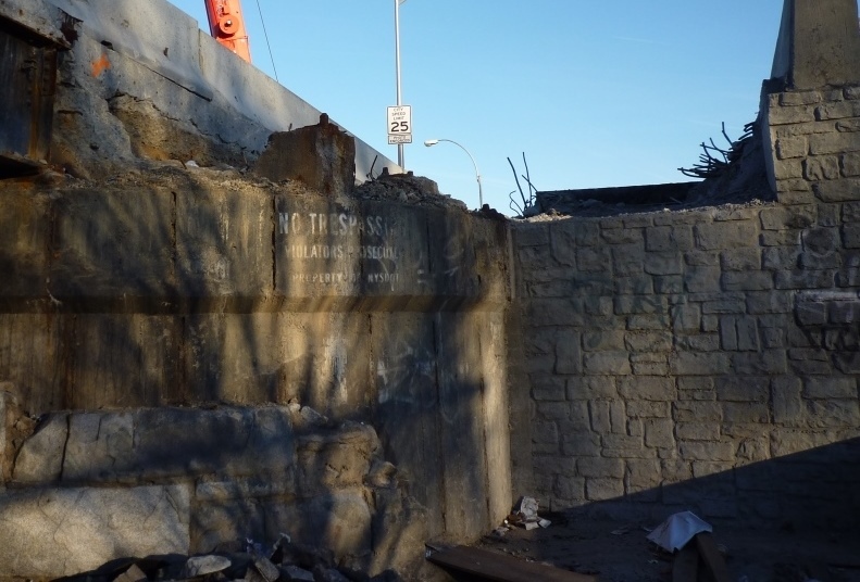
P1090361_sfwmhf.jpg
 
Replies continue below

Recommended for you

Six feet high sheeting walls rarely need bracing unless you can't get the soldier beams down sufficiently below the excavation subgrade. Is the foundation mat preventing installation of the soldier beams? If so, how were you planning to get the Section 1-1 soldier beams down to 2 feet below the demo limit? You may be able to drill in micropile soldier beams that can cantilever without bracing.

In my experience, stacked mafia blocks usually have an insufficient safety factor for sliding unless they are about 4 feet wide, front to back, and unless the retained height is lass than about 4 to 6 feet. This is especially true when the stacked block wall needs to support a traffic surcharge.

 
For an 8 ft. depth (after demolition) and a short cantilever (6 ft. to 9 ft. +), I don't have a problem with the basic proposal. This assumes the uncantilevered length of the wales is at least twice the cantilever length.

What I don't like is the skewed brace and the apparent random location of the braces (for this cantilever loading). I would put all braces (horizontally) perpendicular to the wales and position them directly opposite the driven piles. This would make the wale loading easier to predict. Other than that, don't have a good reason for my suggested brace placement... just seems to be the right thing to do in this situation.

Cantilever_Wall_-1_aao8sx.png


[idea]
[r2d2]
 
PE - The restrained fill will be about 6' max. I did a design for unbraced sheeting, using the simplified method, then embedment was about 11', putting the tip close to the mat.however, the contractor prefers to use soldiers & lagging. He has a bunch of 10' W12's in stock.

SRE - I don't like the skewed brace either. Turning it back to get an end support would be tough. After the "cantilevered" wall I was going to place the braces perpendicular to the walkers and support them against the wing wall. I'm a little less wary of the idea now. I might be able to temporarily tie the end pile to the stringer, to give the end section more support.
 
A 6' high soldier beam/lagging wall should not need bracing or wales unless you can't get sufficient toe embedment. The "problem" here seems to be that the contractor wants to use short soldier beams that he already owns. If he needs only a handful of soldier beams, it would probably be cheaper to buy new beams with the proper length to cantilever rather than to install and remove wales and braces. The excavation would also be cheaper with cantilevered soldier beams (no brace or wale obstructions). I would be interested in seeing how you came up with the 11' of toe embedment. Did you divide the passive earth pressure coefficient, Kp, by a safety factor or did you use the full Kp and then increase the embedment as described by Teng in his simplified design method?

 
PE - I got to 11 by reducing the passive pressure by 1.5, per the spec, then adding 20% to the theoretical depth, again per the spec. I can use a 1.25 SF on the passive pressure for temporary condition but it only saves a foot.

I would prefer soldiers without wales & bracing. There's only 16' from top of pavement to top of footing; so the pile tip is on the footing. Might be able to sharpen my pencil and make it work. The wall is probably 20' long tops.
 
I can see why you got 11' of embedment. If that's what the specs require, you may be stuck with it, but that method does not follow Teng's simplified method for cantilevered sheeting design. Are you reading actual design specs or just geotech report recommendations which may not be binding. Read carefully the specs. Do they present requirements or recommendations?

 
PE - I have to follow the DOT spec. It's possible their "simplified method" is a little different from Teng's "Simplified Method". I'm going to look at the old US Steel manual example and compare the two. Meanwhile, we may have a solution without walers and bracing: Bolt the soldiers to the 12" reinforced concrete pavement at the top of the wall.

 
Status
Not open for further replies.

Part and Inventory Search

Sponsor