OzGuy
Electrical
- Apr 8, 2014
- 10
Hi,
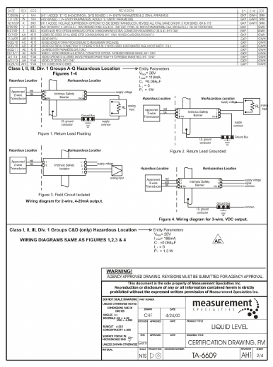
We have an application of sending a non-IS signal between two building, using exiting IS cabling through a hazardous area. I am thinking of using one IS barrier isolator at each end.
Typically, in an IS system, there is a barrier isolator inside a safe area. The non-IS side of the barrier is connected to the control or safety system, and the IS side is connected to a field instrument in the hazardous area.
In our case, the two ends are both in safe areas (two different pressurized buildings - Ex p) but the existing multipair wiring between the two is IS. Using a single barrier isolator at one end (system termination side) is not sufficient, as the IS circuit needs to be connected to an IS certified device at the other end (or a simple device, like an RTD – but it is not our case). Since the other end is not an IS device, I suggest using a second isolator barrier where the two IS sides of the two barriers are connected to each other.
For a 4-20mA signal, one sinks the current and the other one sources. The IS calculations would be very easy using the other barrier parameters as the field device parameters for the other barrier. It is easier for a digital signal, as one side will have a DI barrier and the other one will have a DO barrier with a dry contact relay which is a simple device. All governed by IEC 600879 series.
Does the above make sense? Appreciate if you could share your thoughts.
Thank you!

