Continue to Site

Eng-Tips is the largest engineering community on the Internet

Intelligent Work Forums for Engineering Professionals

  • Congratulations KootK on being selected by the Eng-Tips community for having the most helpful posts in the forums last week. Way to Go!

Use steel on compression face to Increase phi Mn?

Status
Not open for further replies.

Blackstar123

Civil/Environmental
May 5, 2013
253
I have a two story RCC structure with multi bays in X direction and single bay in Y direction. The building LRFS is IMRF. Flexure demand on the beams in Y direction due to seismic loads is coming out to be very high such that some compression reinforcement will be required for -Mu. The span of beam is 10.5m

This is what the design forces at the support looks like.

Size of beam = 400x1200
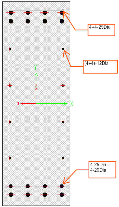
Required +Mu = 1180 KN-m, As reqd = 2961 mm2, Provided: 4-25Dia + 4-20Dia
Required -Mu = 1680 KN-m, As reqd = 4861 mm2, As’ = 30 mm2, Required No, of bars = 12-25Dia

I cannot increase the size of beam due to clear height requirement (i.e., 5m) but also don’t want to provide maximum steel on the tension face of beam.

If I only provide 8-25Dia on tension face and take advantage of skin reinforcement and the steel present in the compression zone, numbers are showing me some decent increase in flexure capacity of the beam, due to compression force in the steel in compression zone (i.e., 4-25Dia + 4-20Dia).

Capture_or8lwx.png


I would like to ask for advice from experts here if they think this approach is workable.
 
Replies continue below

Recommended for you

Absolutely. Steel in compression should be confined well by transverse reinforcement, but you're likely to have that anyway for shear and ductility purposes.

If the steel is there, use it!

----
just call me Lo.
 
Concur... the compression steel markedly adds to the ductility of the concrete members.

Rather than think climate change and the corona virus as science, think of it as the wrath of God. Feel any better?

-Dik
 
I tend to ignore the effect of compression steel in the early phase of design and size my beams that way.

But, later on, if I determine I need a little more capacity, I take advantage of every bar in the beam.... keeping in mind that this will affect development and termination of bars and such.
 
Thank you all for your opinion, it's greatly appreciated.
 
That's a lot of steel in a small beam. Make sure the beam/column joint can physically be built. Sometimes the bar arrangement between the column verticals and the beam longitudinal bars is the limiting factor.
 
The only capacity increase you get is because the neutral axis depth is reduced so the C-T lever arm is increased.

The steel compression shown above looks high for the compression zone steel you have supplied. What strain has been used for the different layers of compression steel.

Presumably you have 4 25dia at the bottom at about 60mm from the compression face then 2 layers of 2 20dia as side face reinforcement. I doubt any of the side face reinforcement is actually in compression with a neutral axis depth of 186.1mm
 
JLJN said:
That's a lot of steel in a small beam.
You're right, this is a lot of steel for the beam size. I usually keep the steel percentage in beam within 0.6%. But I would not call this a small beam. I was actually anticipating a call from client to provide justification for the size of beam. It definitely caused some people to raised their eyebrows in my office.

JLJN said:
Make sure the beam/column joint can physically be built. Sometimes the bar arrangement between the column verticals and the beam longitudinal bars is the limiting factor.
Clear spacing between the bars is within the recommended spacing. Thank you for the suggestion, I'll surely keep it in mind.

Rapt said:
The only capacity increase you get is because the neutral axis depth is reduced so the C-T lever arm is increased.
Thank you for providing your insight. Yes you're absolutely right. It was implied that less concrete is required to balance the tension force because of significant contribution from steel in compression.

Rapt said:
...then 2 layers of 2 20dia as side face reinforcement. I doubt any of the side face reinforcement is actually in compression with a neutral axis depth of 186.1mm]
No, 4-20Dia are all near the bottom face. I actually didn't specify the side face reinforcement in the OP. I hope the following picture makes it clear. The results are ok. I've actually verified my manual calculation from sap2000.
Capture_qvqxc7.png
 
Mr Blackstar123 (Civil/Environmental),

If i were in your shoes, i would try the use of SMF instead of IMF . When you use IMF , R=5 and for SMF R= 8. Another option, the use of Dual System with Special Walls to get reasonable beam and column moments..

My concerns are,

- Beam- column joint detailing requirements,

- You SHALL provide strong column- weak beam ..

You may consider to provide more info ( structural plan, size of columns etc..) to get more useful replies..
 
HTURKAk said:
...You may consider to provide more info ( structural plan, size of columns etc..) to get more useful replies ]

As I've mentioned, this is a 2 story building with a single frame along the axis under consideration (thus, dual frame is not possible). Span of the frame is 10.5 m. Bottom story height is 6.2m and top story height is 5m. One column of the frame is supporting PEB column at roof level.
Supplier has given a seismic shear of 320 KN at top of that column. This is almost as much as the seismic shear on the rcc frame alone. Therefore, I wouldn't get as much advantage by increasing the R value as one would expect. Not to mention the impact special detailing will have on project cost.

Rest assured, strong column-weak beam checks have been performed. I've provided 20% more flexure capacity in columns.
Column size is 600x1000.
Beam column joint conjestion concerns are real. I would look deeper into this on next working day.

Thank you for taking an interest in my problem. I really appreciate it.
 
With the bar arrangement as shown, 500 MPa steel and 30 MPa concrete I get phi.Mu values of 1945 kNm without the compression steel and 2039 kNm including it, which is less than a 5% increase. With higher strength concrete the difference is even less, because the neutral axis is almost on the level of the inner layer of compression steel. The difference from including the side face steel was much greater, but even with just the 8 25 mm tension bars I get 1791 kNm which is well over your required value. The required number of tension bars in the OP looks much too high.

Doug Jenkins
Interactive Design Services
 
IDS,
Thank you so much for commenting. I performed the same exercise before posting here. I got the required phiMn when i considered both the side face reinforcement and reinforcement at compression face.
I'm aware that I'm only saving 2-25Dia bars by performing this whole exercise.

Compressive strength of concrete in beams is 16.5 MPa and yield strength of bar is 410 MPa, though.
 
What code allows you to use 16.5MPa concrete as structural concrete?
This seems extremely low and at least in this part of the world a minimum of 25MPa is required.

Most of the flexural strength improvement you're seeing will be from consideration of the side bars as tension reinforcement, not from the compression bars being considered.

 
Blackstar 123 said:
Compressive strength of concrete in beams is 16.5 MPa and yield strength of bar is 410 MPa, though.

OK, with those properties both the compression steel and the side face steel increase the design ultimate capacity by about 10%, or about 18% increase for the two combined.

I thought the tensile steel force shown in the output in the OP was for the tension face steel only, but if the side face steel is added in I get close to the same values using the 410 MPa yield stress.

I agree with Agent666 about the low concrete strength. I have never seen that low a strength used for a flexural member anywhere or any time over the last 50 years.

But getting back to the original question, yes if including the compression and side face steel increases the design capacity to the required level, then certainly it is OK to include it. In fact I include all the steel in my calculations as a matter of course anyway.

Doug Jenkins
Interactive Design Services
 
Agent said:
What code allows you to use 16.5MPa concrete as structural concrete?
This seems extremely low and at least in this part of the world a minimum of 25MPa is required.

Design is based on the provisions of ACI 318-19. Structure is assigned to seismic design category C and there are no special material strength requirements for this category in ACI.
That being said, concrete compressive strength of 16.5 MPa is being used in beams and slabs only. Rest of the structural component have a minimum cylindrical strength of 27.5 MPa.
 
I thought ACI had a hard lower limit of 2500psi or 17.5MPa on the concrete strength for structural members (ACI isn't my design code, but I am reasonably familiar with it as our own code (NZ) is based on older versions of it)?

I think going that low just makes other things hard, for example durability, long term effects/deflections of slabs/beams, design of fixings, transmission of axial loads through floors, design of beam/column joint regions, etc.

I'd also note you don't comply with the 0.7f'c limit in 15.5 for axial transmission through floor systems, so that makes construction on site very much harder to follow the provisions within that clause for column axial transmission through the floors, and you're effectively limiting the column strength to the 16.5MPa as it points out if you're pouring the weaker beam/slab mix through the beam/column joint zones, so you have to ask yourself what was the point in going higher strength in the columns as you're not seeing the benefit of it.....

Given you profile states you're in Pakistan I can't imagine the onsite QA is that great to ensure they will follow those requirements/provisions in clause 15.5 to ensure that the column mix goes 2 ft out into the slab for example? And generally, this goes against the normal way people would construct and pout beams and slab on top of columns. I'm reluctant to specify it in an environment where there is QA available to make sur eit is done, because quite frankly it is a major pain in the butt for the people pouring the beams/floors.

My personal preference is to always more closely match the beam/column/slab concrete strengths. Less issues on site preferred any day of the week for me.

 
I thought ACI had a hard lower limit of 2500psi or 17.5MPa on the concrete strength for structural members
Can you provide the reference for this? I looked it up in the ACI code but could not find it.

I think going that low just makes other things hard, for example durability, long term effects/deflections of slabs/beams...
I completely agree with you on this. In fact, I remember doing battle on same of these points with my boss when I first started working at this firm. I did try to sell him on the construction feasibility aspect but his end argument was how they handle it on site is not our responsibility. His concern was more about the economical aspects of the material quantity related stuff. My firm is an old one (50+ years) and well renowned in this part of the world. As far as I know, they have been specifying this concrete strength for low to moderate exposure conditions since the start of time and to my knowledge have had no complaints about the serviceability or intended performance of structures. I believe they probably did the math to get the right strength at the best possible price point.

As for the QA aspects of the project, my firm specialized in large-scale projects where client normally has an in house team of technical experts from all major fields (mechanical, electrical and civil) or sometimes hired external private inspectors to conduct the on-site inspections.

.. they will follow those requirements/provisions in clause 15.5 to ensure that the column mix goes 2 ft out into the slab..
I think this clause is specified somewhere in the general note documents. However, on a safer side I’ll specifically specify this provision on the drawing sheet also.

.. because quite frankly it is a major pain in the butt for the people pouring the beams/floors.
Believe me I can imagine. But it's really difficult to change people minds about their long held beliefs.
 
Wow... 16.5 MPa concrete.

I haven't seen anything that low before, and I've been looking at some 100+ year old bridges.

I once proposed to use 32 MPa concrete for some bored piles in non-aggressive soil, which would supposedly satisfy a 100 year design life according to our code. My superior looked at my like I was insane. 40 MPa is specified as a bare minimum for absolutely everything in my world. Even where 25 MPa or 32 MPa would satisfy the durability requirements, 40 MPa is invariably specified and nobody seems to bat an eyelid at whatever additional cost/environmental impact involved.
 
Spend huge dollars on forming, and rebar, but we gots to save that 3-5% on the important part. Egad.
 
I suspect even in Pakistan, the labor cost vs. material cost balance has shifted significantly towards the labor being comparatively much more expensive than it used to be. It might be time to reexamine the cost ratio.

As an example, we've got a lot of steel girder bridges in our inventory with thin (5/16") webs and vertical stiffeners every 3' or so, a hundred or more per girder. However, the ones we've designed in the last 20 years all have webs thick enough they require 5 or 6 stiffeners at most. Most don't require stiffeners at all. The extra steel is far cheaper than skilled labor for the welding.

Rod Smith, P.E., The artist formerly known as HotRod10
 
Status
Not open for further replies.

Part and Inventory Search

Sponsor