Eng-Tips is the largest engineering community on the Internet

Intelligent Work Forums for Engineering Professionals

  • Congratulations waross on being selected by the Tek-Tips community for having the most helpful posts in the forums last week. Way to Go!

Using busbar as Shunt resistor for current measurement 2

Status
Not open for further replies.

Managuensis

Automotive
Jun 10, 2022
11
0
0
EE
First of all, plz excuse my incorrect terminology and schematics as I am actually a mechanical engineer.

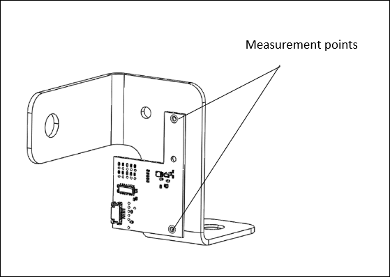
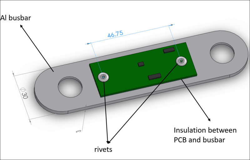
We are trying to measure the operating current of a DC battery without using a Shunt resistor. The existing terminal busbar will serve as the Shunt resistor. A custom PCB carrying a highly advanced SoH chip will measure the voltage drop across two spots on the busbar. Then based on Ohm's law, the current will be calculated by dividing the voltage drop with the equivalent resistance between the measuring points. The rated operating current interval of the battery is 0 to 1 kA. The aim of the measurement is to monitor the state of health of the battery. My task is to determine the right measurement setup on the busbar. I expect 4 factors that create difficulty for accurate measurement:

[ol 1]
[li]Measuring the voltage drop of a busbar from two spots 46 mm apart on the outer surface: Given that current will propagate in a highly complex way through the entire cross-section of the busbar, is this a good idea?[/li]
[li]The theoretical voltage drop between the shown spots, based on the lowest series current and calculated resistance of busbar can be as low as 1 mV. Is it possible to get accurate measurements of such V magnitude with the given setup?[/li]
[li]The busbar will heat up due to high current value, up to 80°C. How would temperature increase affect the voltage across the two spots?[/li]
[li]As the Al busbar has material defects inside and on the outside, how would this affect the accuracy of the measurement?[/li]
[/ol]


Screenshot_2022-10-27_191937_cwsfkp.png
 
Replies continue below

Recommended for you

Dear Mr.Managuensis (Automotive)(OP)27 Oct 22 17:24
"... My task is to determine the right measurement setup on the busbar. I expect 4 factors that create difficulty for accurate measurement:
#!. Measuring the voltage drop of a busbar from two spots 46 mm apart on the outer surface: Given that current will propagate in a highly complex way through the entire cross-section of the busbar, is this a good idea?

Any not be a problem as you are measuring dc, where "skin effect" is not significant.
#2. The theoretical voltage drop between the shown spots, based on the lowest series current and calculated resistance of busbar can be as low as 1 mV. Is it possible to get accurate measurements of such V magnitude with the given setup?
The voltage of 1 mV may be too low. A value of 50, 75 or 100mV would be better (to avoid interference).
#3. The busbar will heat up due to high current value, up to 80°C. How would temperature increase affect the voltage across the two spots?
As the Al busbar has material defects inside and on the outside, how would this affect the accuracy of the measurement?

The current is 0-1kA, temperature may be up to 80 [sup]0[/sup] C. Temperature coefficient of Al alloy is about 2x 10[sup]-3[/sup] (K[sup]-1[/sup]). This is very Unfavorable as a shunt material. Most shunts are of alloy e.g. Manganin with Temperature coefficient of 0.01 x 10[sup]-3[/sup] (K[sup]-1[/sup]). Attention: at 80[sup]0[/sup] C, thermal draft starts. Suggest to use a commercial shunt rated for 2kA 100mV. This will not heat up at 1kA and yet has sufficient mV for not required a sensitive voltage detection.
Che Kuan Yau (Singapore)

 
Measuring the voltage drop of a busbar from two spots 46 mm apart on the outer surface: Given that current will propagate in a highly complex way through the entire cross-section of the busbar, is this a good idea?
Complexity is not a concern as much as repeatability; if the measurement is repeatable, you can "calibrate" for the non-uniformity

The theoretical voltage drop between the shown spots, based on the lowest series current and calculated resistance of busbar can be as low as 1 mV. Is it possible to get accurate measurements of such V magnitude with the given setup?
A decent meter can measure down to the microvolts, and a laboratory grade meter could measure nanovolts; much can be mitigated with averaged measurements over time

The busbar will heat up due to high current value, up to 80°C. How would temperature increase affect the voltage across the two spots?
calibration over temperature can potentially correct or mitigate that

As the Al busbar has material defects inside and on the outside, how would this affect the accuracy of the measurement?
again, calibration can deal with that


TTFN (ta ta for now)
I can do absolutely anything. I'm an expert! faq731-376 forum1529 Entire Forum list
 
@ Mr. IRstuff (Aerospace)
#1. "....if the measurement is repeatable, you can "calibrate" for the non-uniformity..."
Unless you are a manufacturer, designing this shunt; "calibrate" it yourself with one and the only one piece with say Class 0.1 measuring instruments and laborious calibration process would be far too costly to be considered.
#2."... A decent meter can measure down to the microvolts, and a laboratory grade meter could measure nanovolts; much can be mitigated with averaged measurements over time"
These down to microvolt laboratory instruments would cost you a bomb !.
#3. Opinion: Al is NOT a good material to be used for manufacturing it into a shunt.
#4. Conclusion: It would be cost and labour saving to buy the standard product on the market instead of " reinventing the wheel".
Che Kuan Yau (Singapore)
 
I see a few problems, which I suppose you have looked into. One being that it only takes a fraction of an Ohm to measure, and the signal can be amplified with an Op-Amp. The other is the power supply for the circuit. And maybe another one is where is the signal to be displayed or impressed?
If it were to be powered by the voltage drop, and to emit a radio signal (such as a wi-fi or something like that), that would be an impressive device.
 
Now what if the busbar is a bent shape such as the one below. How would the repeatability change, compared to the prismatic busbar in the original post?

Screenshot_2022-11-27_230700_cu5aam.png
 
Status
Not open for further replies.
Back
Top