Managuensis
Automotive
First of all, plz excuse my incorrect terminology and schematics as I am actually a mechanical engineer.
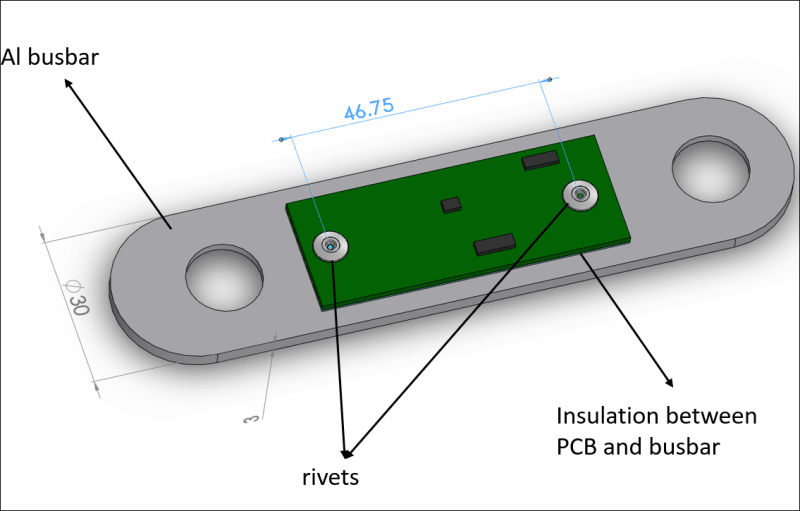
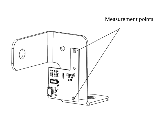
We are trying to measure the operating current of a DC battery without using a Shunt resistor. The existing terminal busbar will serve as the Shunt resistor. A custom PCB carrying a highly advanced SoH chip will measure the voltage drop across two spots on the busbar. Then based on Ohm's law, the current will be calculated by dividing the voltage drop with the equivalent resistance between the measuring points. The rated operating current interval of the battery is 0 to 1 kA. The aim of the measurement is to monitor the state of health of the battery. My task is to determine the right measurement setup on the busbar. I expect 4 factors that create difficulty for accurate measurement:
[ol 1]
[li]Measuring the voltage drop of a busbar from two spots 46 mm apart on the outer surface: Given that current will propagate in a highly complex way through the entire cross-section of the busbar, is this a good idea?[/li]
[li]The theoretical voltage drop between the shown spots, based on the lowest series current and calculated resistance of busbar can be as low as 1 mV. Is it possible to get accurate measurements of such V magnitude with the given setup?[/li]
[li]The busbar will heat up due to high current value, up to 80°C. How would temperature increase affect the voltage across the two spots?[/li]
[li]As the Al busbar has material defects inside and on the outside, how would this affect the accuracy of the measurement?[/li]
[/ol]


