Continue to Site

Eng-Tips is the largest engineering community on the Internet

Intelligent Work Forums for Engineering Professionals

  • Congratulations KootK on being selected by the Eng-Tips community for having the most helpful posts in the forums last week. Way to Go!

VALIDATE RESULTS NASTRAN AND ABAQUS 2

Status
Not open for further replies.

Giang123

Aerospace
Sep 14, 2023
16
Hi all,
Currently, I am validating between MSC NASTRAN software and ABAQUS software. I import a BDF file into ABAQUS; however, the ABAQUS results differ by 19% compared to MSC NASTRAN. So, I'm not sure if there's anything specific to consider when importing a BDF file into ABAQUS. I have attached the BDF file below.
 
 https://files.engineering.com/getfile.aspx?folder=38ac3e06-aa48-47ee-815c-a8ab7354bdb2&file=Model_BEAM.bdf
Replies continue below

Recommended for you

Can you share the .cae or .inp file too ? I only have access to Abaqus but I can take a look and see if there are any big mistakes.

Some screenshots from both applications would also help.
 
My model consists of a shell and BEAM with a cross section L. I only solved for selfweight to validate the results. You can find the attached input file below and the results from NASTRAN and ABAQUS.
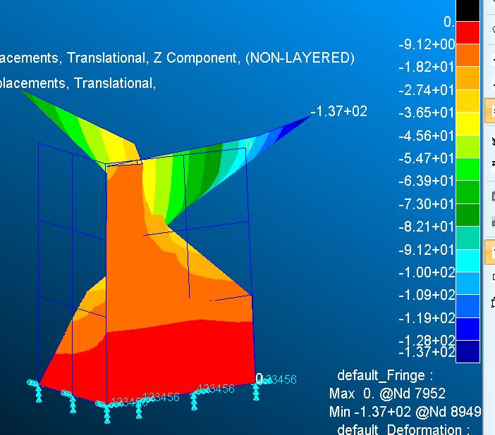
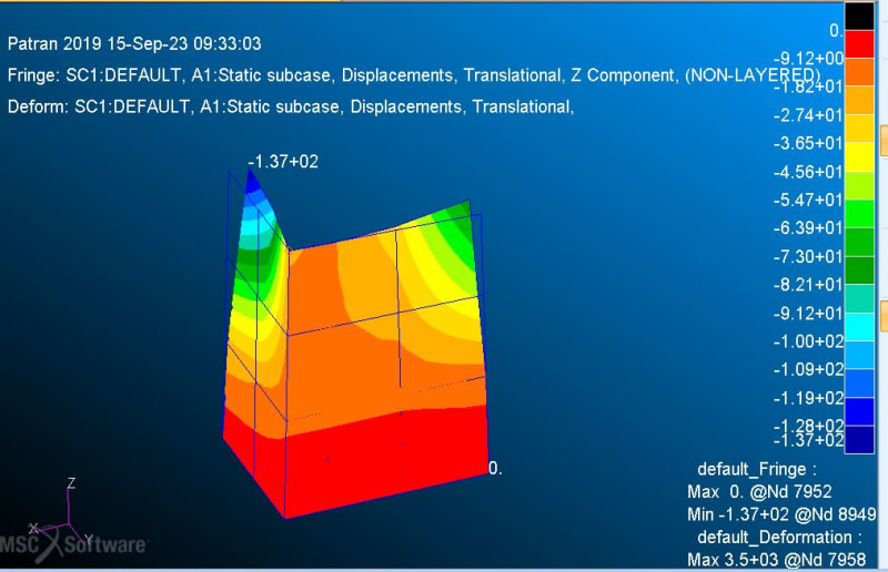
MSC NASTRAN software
MSCNASTRAN_atyqz0.jpg

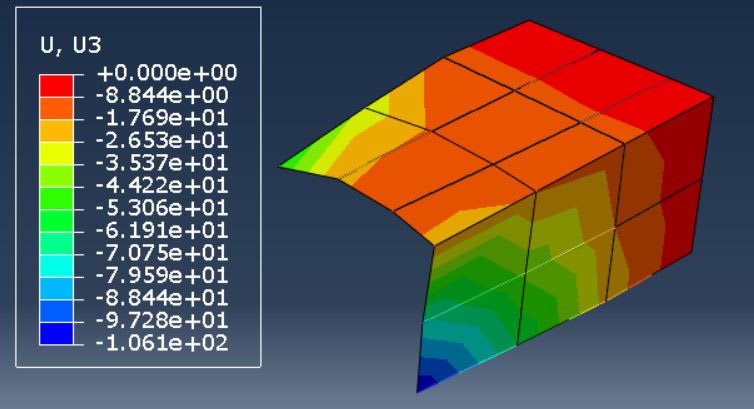
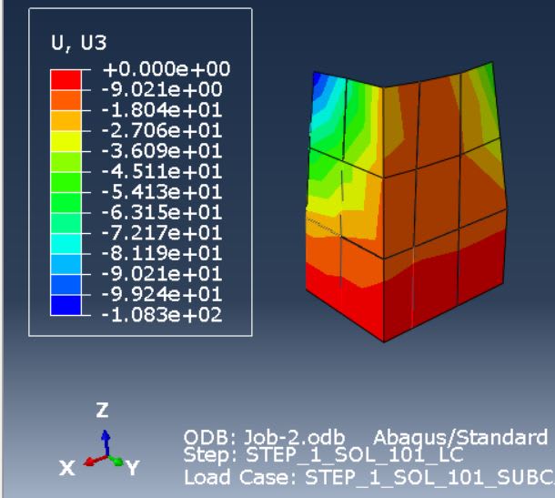
ABAQUS software
ABAQUSU3_kgvyfk.jpg
 
How about posting a pdf or jpg so folks without NASTRAN and ABAQUS can comment?

Without seeing it, my first question is: Have you compared the program output to a simple problem with known results from manual calcs or textbook example? If your problem is more complicated, then back up to an easy problem first.
 
I'll point out that the two output plots look like they are oriented differently relative to the direction of gravity.

My opinion on this:
1) Don't start with comparing the FEM contours. Instead, start with comparing joint deflections, joint reactions and such. Also, can you force the scale of the deflection plot to be in the same range?
2) If the joint reactions and joint deflections are approximately the same then you know the models match pretty well. It becomes a discussion about how the contour algorithms work. Maybe even how the elements orientation defaults could be different.
3) I suspect you're going to see the joint reactions going in different directions based on those two plots.
 
Which of the two is correct, or at least close, based on a manual calculation?
 
I'd compare the two codes using a single element patch test ... different element geometries, different loads ... see how the elements react.

that MSC pic looks "wrong" ?

"Hoffen wir mal, dass alles gut geht !"
General Paulus, Nov 1942, outside Stalingrad after the launch of Operation Uranus.
 
Hi all,
I apologize for not being clear in describing the results above. You can see the image below because I am using a BDF file from MSC NASTRAN to import into ABAQUS, so there should be no difference between NASTRAN and ABAQUS in terms of settings and force directions.
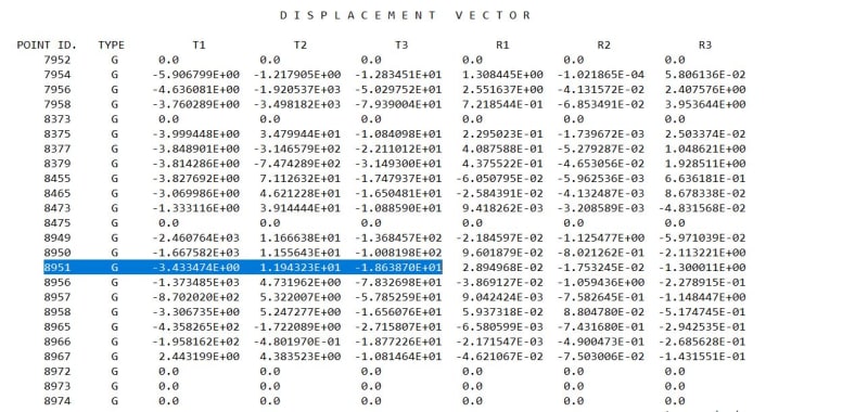
Displacement at NODE 8951 in MSC NASTRAN = -18.6387mm.:
N1_ddw5zv.jpg

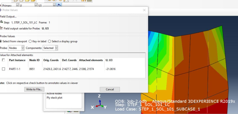
Displacement at NODE 8951 in ABAQUS = -21.0616 mm:
A1_usdqfl.jpg

Output displacement Z direction in ABAQUS:
ABAQUSU3_qnx0kq.jpg

Output displacement Z direction in MSC NASTRAN:
N2_s0kj2s.jpg

The displacement at node 8951 differs between the two software packages, even though I am using the same BDF file. So, I believe there might be some differences between MSC NASTRAN and ABAQUS that I am not aware of. I am aware of the difference in shell elements, specifically S4 and S4R, and I have tried to adjust them, but the results still do not match.
 
I tried setting the density of CBEAM to 0, and the results matched. I'm not sure if there are any differences between ABAQUS and NASTRAN regarding the CBEAM element (I'm using a first-order beam element). Is it related to the mass matrix or not, or mesh. It may be related to algorithms.
 
CBEAM ? those look like QUADs ?

the elements could easily have different formulations, try doing a single element patch test.

"Hoffen wir mal, dass alles gut geht !"
General Paulus, Nov 1942, outside Stalingrad after the launch of Operation Uranus.
 
I have mentioned before that my model includes SHELL and BEAM cross sections L. I have conducted the following test cases, and the results differ by only 1 to 5%:
- Model with only shell elements.
- Model with only L-shaped beam elements.
- Model with both shell elements and one L-shaped beam.
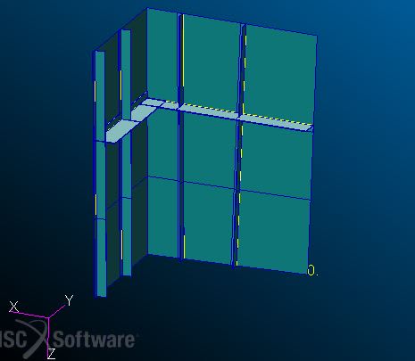
Model in MSC NASTRAN with five cross section showed
3_lfqc1a.jpg
 
Giang123 said:
Is it related to the mass matrix or not, or mesh.
Is this a dynamic analysis? If not, that doesn't matter.

Regarding the mesh, you should be able to extract all node coordinates in both ABAQUS and NASTRAN and in that way ensure that the element sizes and locations are identical in both models. Unless these softwares support 100% manual meshing, you should probably start with something more simple (e.g., flat panel with one rib) to ensure that the automeshing results are similar for both softwares.

Connections of the ribs to the shell might also cause differences in the results. Based on the figures you've shown, the beam profile neutral axis is not in the shell mid-plane and some sort of offset has been applied.

Giang123 said:
first order beam element
Have you looked into the documentation to find out exactly what element formulation ABAQUS and Nastran are using for the beams and the shells? A <=5% difference could be explained by element order or method of avoiding shear locking.

Also, as JoshPlumSE already mentioned, it is not worthwhile to compare contour plots unless you are sure that they are implemented identically in each software. Are the values averages of integration point values, averages of element mid-point values, averages of nodal values or something else?

PS. You have also not mentioned the analysis type. If it is non-linear in any way, the results could differ due to a multitude of reasons not mentioned so far in this thread.
 
I didn't read through the replies....so someone may have already mentioned this: the mesh looks different (comparing model to model). That's a frequent error I see in what I do (in terms of forces produced and displacement).
 
check the units for mass values, accelerations, applied forces, material properties, etc. and check boundary conditions.

also, what exact element types are you using in Nastran and Abaqus?

 
My mistake for not carefully providing information to everyone, I checked the model information before posting on this forum:
Before posting my question here, I made sure to match the data between the two software regarding mass, center of gravity, net force, and moment.
- ABAQUS and NASTRAN models have the same mesh.
- CBEAM elements are both first-order BEAM elements., SHELL element is S4
- Constraints are the same between the two software packages, and I only solved for selfweight (GRAVITY).
- AND I IMPORTED THE BDF FILE FROM MSC NASTRAN INTO ABAQUS, SO THE SETTINGS FOR BOTH MODELS ARE THE SAME.
MODEL IN NASTRAN:
1_ohg2aj.png

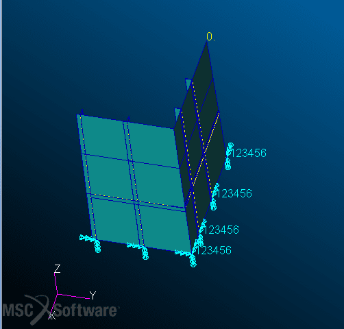
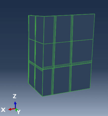
MODEL IN ABAQUS:
2_vx9rtg.png

unnamed_wqbny9.png
 
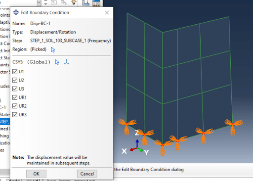
Your figure shows the text "Sol 103 (Frequency"). Is this an eigenvalue analysis for modes of vibration? You will get more useful answers if you explain the analysis type(s): linear static, non-linear static (geometric, material or contact), linear or non-linear dynamic, modal analysis etc.

"- CBEAM elements are both first-order BEAM elements., SHELL element is S4"
A "first-order beam element" can mean many things. Do they incorporate warping? Do they include shear stiffness (timoshenko model) and how do they avoid shear locking? If the analysis is dynamic, is mass lumped or distributed according to the displacement interpolation, and is rotary inertia accounted for? Regarding shell elements, I doubt that both abaqus and msc nastran have a shell element called "S4" that is identical in implementation regarding e.g., measures to prevent shear locking, mass characterization (lumped/consistent, translational only/both translation and rotation) etc., but I could of course be wrong.

I suggest you read the technical manuals or (if the manual is incomplete) contact the technical support to ensure that the elements are identical if you are serious about investigating 1-5% differences in results. The more complicated the problem becomes, the more factors you have to be aware of when validating results, and judging by the posts you've made here, you've forgotten to account for several things.

PS. You are conducting verification. Validation involves comparing empirical testing (real-world behaviour) to predictions obtained with mathematical models.
 
A "first-order beam element" can mean many things. Do they incorporate warping? Do they include shear stiffness (timoshenko model) and how do they avoid shear locking? If the analysis is dynamic, is mass lumped or distributed according to the displacement interpolation, and is rotary inertia accounted for? Regarding shell elements, I doubt that both abaqus and msc nastran have a shell element called "S4" that is identical in implementation regarding e.g., measures to prevent shear locking, mass characterization (lumped/consistent, translational only/both translation and rotation) etc., but I could of course be wrong.

I suggest you read the technical manuals or (if the manual is incomplete) contact the technical support to ensure that the elements are identical if you are serious about investigating 1-5% differences in results.

That's an excellent point as the stiffness of some elements can vary from program to program. And good luck on trying to get shape functions and so forth out of the developers of these programs. They guard them like trade secrets (especially the more complicated elements).....which I guess they are.

 
Giang123 said:
AND I IMPORTED THE BDF FILE FROM MSC NASTRAN INTO ABAQUS, SO THE SETTINGS FOR BOTH MODELS ARE THE SAME
I think that may be where you make the mistake [smile].

You don't say what preprocessor you use. But since you create a file (bdf) for Nastran and import if into ABAQUS you will get whatever interpretation ABACUS/CAE does of that bdf-file. And since the properties for the elements may differ so may the results. I would create one model for Nastran and another for ABAQUS. I would avoid getting Nastran settings into ABAQUS. Unless the purpose is to test how the interpretation works.

Also, I imported your model into Femap. You have a gravity of 9807 so you probably work with metric units (Ton and mm). That means that E should be in MPa, 21000 (you are a factor 10 to low and the same applies for G). And density 8.32e-6 tonne/mm^3 does not seem correct (a factor 1000 to high i think)
 
Hi centondollar ,
My figure shows the text "Sol 103 (Frequency"), which is unrelated. I just took a screenshot to show everyone the model with a cross-section, boundary constraint in ABAQUS. Can you please take a look at the attached .inp file above?

I posted on the forum because I'm new, and I don't have much time to read the manuals for both software packages. So, I posted to see if experienced users could suggest what I should do. Your suggestions could be very helpful to me.
 
Hi ThomasH,
My task requires converting from MSC NASTRAN software to ABAQUS, so I'm using a BDF file for importing. The material information is correct and is in millimeter unit system, provided by a company.
I only use static analysis
 
Status
Not open for further replies.

Part and Inventory Search

Sponsor