Eng-Tips is the largest engineering community on the Internet

Intelligent Work Forums for Engineering Professionals

Validity 4

Status
Not open for further replies.

aniiben

Mechanical
May 9, 2017
158
0
0
US
3DDave said:
Q1 - referring to a datum feature in a way that it was not initially constrained is a potential problem for understanding the condition. See previous discussion where I make clear that Figure 4-16 (c) is clearly evaluated incorrectly in the standard.


Question_-_Copy_db8vkh.jpg


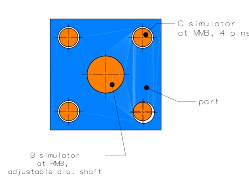
Inspired by a statement made in a previous discussion and also by some of my misunderstandings of the standard’s intent on dealing with datum features of size called at RMB and also at MMB, I would like to ask the members of this forum how would you consider the datum reference frame shown in the embedded picture.

Case 1: A│B│C(M)│
----Datum feature B at RMB (shown in the picture) ---

Is this datum structure or DRF valid? If yes, are there any issues with the violation of datum feature precedence order?

Case 2: A│B(M)│C(M)│
----Datum feature B at MMB (NOT shown in the picture) ---

Same open ended questions as for case#1.
 
Replies continue below

Recommended for you

I would say that option 1 is fine. The tertiary datum pattern C constrains last remaining rotational degree of freedom. In many cases people would just use one of the holes in the pattern as a tertiary datum feature (even the standard does so in fig. 7-55 in Y14.5-2009), but if the real part functions in a way that actually any of the pattern holes might constrain rotation of the part about the secondary datum axis B, then it's kind of illogical to arbitrarily pick just one hole.

I see an issue with option 2 regardless if the drawing is per 1994 or 2009 version of the standard. The issue (that was mentioned in some of the previous threads) is that with |A|B(M)|C(M)| there is no guarantee that datum feature B will always work as translation-constraining feature only and datum feature C will always work as rotation-constraining feature only. Even with no basic location relationship between the datum feature simulators B and C (which was the default condition in '94), the same problem applies.
 
pmarc said:
The issue (that was mentioned in some of the previous threads) is that with |A|B(M)|C(M)| there is no guarantee that datum feature B will always work as translation-constraining feature only and datum feature C will always work as rotation-constraining feature only.

Does B at RFS and C at MMB always guarantee that datum feature B would work as translation-constraining feature only and datum feature C will always work as rotation-constraining feature only?
 
I can imagine as-produced shapes of the secondary datum feature B where referencing it RMB wouldn't constrain both translational degrees of freedom, and therefore the tertiary datum pattern might unintentionally take care of that. Is this what your question is about or you mean something else?
 
I had a different scenario in mind. Datum B will be simulated RMB and datum pattern C will be simulated at MMB by four pins at basic locations relative to B. Under that condition, if one of the datum feature pattern C holes is produced small enough and offset enough from true position so that it is forced to touch the corresponding datum feature simulator pin in a specific place while the adjustable pin B constraint 2 translations of the part, then both B and C will lock rotation together. Therefore B will lock not only translation.
 
That scenario is impossible if |A|B|C(M)| datum reference frame is simulated properly. Or putting it differently, a gage used to simulate that DRF properly should have 4 datum feature simulator C pins that go from the bottom of the datum feature simulator A plane after the part had been immobilized (in terms of translation) by datum feature simulator pin B.

This is called sequential gaging and unfortunately is often ignored by gage designers.
 
Unfortunately, I fail to understand how sequential gauging resolves the issue I described. Suppose datum A and B simulators engage with the part before C does. Once B is engaged, rotation around the axis of B is uncontrolled and translations perpendicular to the B axis (and A plane) are constrained. Once C is engaged, rotation around the axis of B may be constrained by both B and C together rather than by C only. This behavior should ideally be imposed only by |A|B - C(M)|* DRF, but there seems to be nothing that can prevent it for the |A|B|C(M)|* DRF where it is not wanted. Where am I wrong?

* Edit: forgot datum A, now added.

20190414_074515_jih0rc.jpg
 
Sem_D220 said:
Once C is engaged, rotation around the axis of B may be constrained by both B and C together rather than by C only.

I'm afraid I don't understand this. I would say that both B and C might constrain rotation if rotation relative to any axis different than datum axis B was considered.
 
Then I should clarify and rephrase:
One of the axes of the established DRF is going to be coincident with the B axis (2 planes of the DRF will intersect at it). Let us decide that this specific axis of the DRF is the "Z" direction axis. I say that for the as-produced part shown in my figure above the "w" rotation is constrained by the both B and C(M) (as in |A|B-C(M)| ...) and not just by C(M),(as in |A|B|C(M)|...), even though the gage is adequate for the DRF and the simulation is done at the correct sequence per your explanation. Note that by "w" I actually mean rotation about any axis parallel to the B axis (obviously).
 
Sem_D220 said:
Note that by "w" I actually mean rotation about any axis parallel to the B axis (obviously).
And that's the whole problem. As long as you think of "w" this way, B will be always constraining rotation.

But that's not how it should be interpreted - "w" is specifically a rotation about datum axis B and not about any axis parallel to B.
 
pmarc said:
but if the real part functions in a way that actually any of the pattern holes might constrain rotation of the part about the secondary datum axis B, then it's kind of illogical to arbitrarily pick just one hole.

And by doing so (picking just one hole) will make the part / design more stringent than it’s necessary.
Am I correct?


Interesting enough, fig 7-55 has been revised in 2018 (new fig 10-55), but the same datum concept has been kept (the changes were to add MMB’s -B(M) and C(M) - in the profile callout, instead of RMB’s)

Also the equivalent of 4-16 / 2009 figure (which is 7-22/2018) the main “moaner” of the described issue (violating datum precedence order) also stayed somewhat unchanged (“improved” with derived median line straightness).
 
Did they fix the crosshatching in figure 10-55? It was wrong in 7-55. I guess now there is a simultaneous requirement locking the hole pattern tolerance to the surface profile tolerance.

I just looked at the ASME Table of Contents for '2018 and did not see any helical datums. Did I miss it? There are a lot of times one needs to control a feature relative to a screw thread and ASME doesn't seem to care to cover that case.
 
3DDave -- interesting catch about the cross-hatching. But regarding screw threads as datum features, they of course have the screw thread rule (paragraph 5.10) and then an example shown in Fig. 10-36. Other than that, the standard appears to punt on the other details, referring the reader to ASME B1.1 and B1.13M.

John-Paul Belanger
Certified Sr. GD&T Professional
Geometric Learning Systems
 
greenimi said:
And by doing so (picking just one hole) will make the part / design more stringent than it’s necessary.
Am I correct?

I would say it's rather the opposite. Attached is a quick graphic prepared to show how I see this.

All three pictures show the same as-produced version of a plate. Secondary datum axis RMB is derived from the hole in the center. Pictures A and B represent scenario where only the bottom hole in the pattern of four holes has been defined as tertiary datum feature at MMB. Picture C represents scenario where the entire pattern has been defined as tertiary datum feature at MMB.

The actual geometry is such that:
- RAMEs of the top, left and right hole in the pattern have been produced at MMB size;
- RAME of the bottom hole in the pattern has been produced at LMB size;
- All four holes are located exactly at their true positions wrt |A|B|;
- The upper face, nominally horizontal, has been produced in a way that it doesn't fit inside the tolerance zone (profile wrt |A|B|C(M)|) depicted by the two red lines, when the part is mounted in a gage in initial position, as shown in picture A.

As shown in picture B, when only one of four holes in the pattern has been defined as tertiary datum feature at MMB, it may be possible to bring the upper face of the part into the profile tolerance zone by rotating the part about datum axis B until a contact with simulator pin C is achieved. When the entire pattern has been defined as tertiary datum feature at MMB, such rotation may be impossible, as shown in picture C.
 
JP - I mean that as the thread advances that other features are tied to that motion; nothing to due with any aspect of the thread form. I should be able to say that a certain feature is aligned in a certain manner relative to the phase of the datum helix.
 
pmarc,

Interesting point, I would say that means that specifying the entire pattern as a datum feature would have a higher probability of being more stringent, as you could still have a situation where all 4x holes come out at/near LMB to allow the same amount of rotation but as there have been more constraints added (read: variables - not constraints as in DOF) there is a higher chance that at least one of those holes will come out at/near MMB which limits this rotation.
 
pmarc said:
Quote (greenimi)

And by doing so (picking just one hole) will make the part / design more stringent than it’s necessary.
Am I correct?

I would say it's rather the opposite.

Thank you very much pmarc for your explanation.

Sometimes being wrong is more rewarding than being correct, as I learn something new from this thread. Looks like I was incorrect (again) in my previous post.

I was stack in the simultaneous requirement paradigm. I remember one of the previous discussions within which has been concluded that if a random hole (feature) is chosen as a clocking datum feature (for the CMM measurement purposes/ request) and the other holes (features) are the controlled ones, then the design is more stringent than the option where simultaneous requirements is let to drive (and all the holes/features are controlled feature).
Obviously, here the scenario is different but nevertheless I got confused. Well..., live and learn.

Thank you again for straighten me out.


chez311 said:
Interesting point, I would say that means that specifying the entire pattern as a datum feature would have a higher probability of being more stringent, as you could still have a situation where all 4x holes come out at/near LMB to allow the same amount of rotation but as there have been more constraints added (read: variables - not constraints as in DOF) there is a higher chance that at least one of those holes will come out at/near MMB which limits this rotation.

I agree with this description. I would just like to add for clarity that the bottom hole doesn't have to be at or near LMB and the other three holes don't have to be exactly at or ever near MMB to see the difference between the two ways of calling out the tertiary datum feature at MMB. I used that very special scenario in my example to better show the effect, but I would say the difference will be as long as the size of any of three RAMEs (relative to |A|B|) of the top, left or right hole is smaller than the size of RAME of the bottom hole. And this is quite likely to happen in reality as opposed to the scenario with all four RAMEs produced at exactly the same size.
 
Status
Not open for further replies.
Back
Top