Continue to Site

Eng-Tips is the largest engineering community on the Internet

Intelligent Work Forums for Engineering Professionals

  • Congratulations waross on being selected by the Eng-Tips community for having the most helpful posts in the forums last week. Way to Go!

Validity 4

Status
Not open for further replies.

aniiben

Mechanical
May 9, 2017
158
3DDave said:
Q1 - referring to a datum feature in a way that it was not initially constrained is a potential problem for understanding the condition. See previous discussion where I make clear that Figure 4-16 (c) is clearly evaluated incorrectly in the standard.


Question_-_Copy_db8vkh.jpg


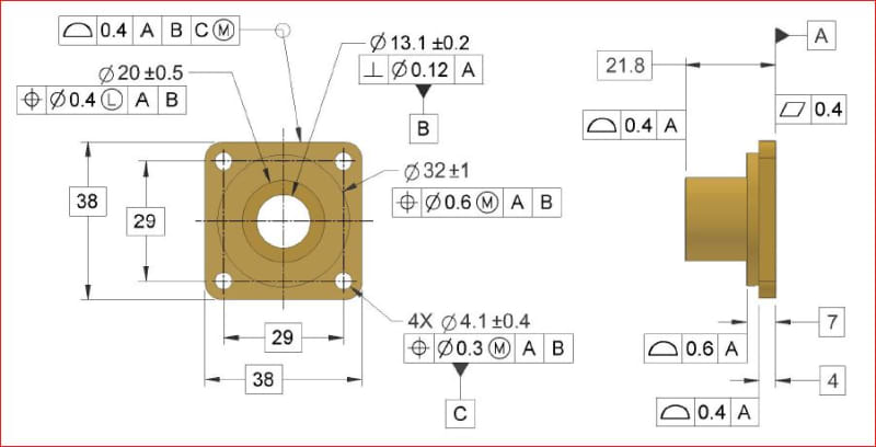
Inspired by a statement made in a previous discussion and also by some of my misunderstandings of the standard’s intent on dealing with datum features of size called at RMB and also at MMB, I would like to ask the members of this forum how would you consider the datum reference frame shown in the embedded picture.

Case 1: A│B│C(M)│
----Datum feature B at RMB (shown in the picture) ---

Is this datum structure or DRF valid? If yes, are there any issues with the violation of datum feature precedence order?

Case 2: A│B(M)│C(M)│
----Datum feature B at MMB (NOT shown in the picture) ---

Same open ended questions as for case#1.
 
Replies continue below

Recommended for you

pmarc 16 Apr 19 15:49 said:
I would just like to add for clarity that the bottom hole doesn't have to be at or near LMB and the other three holes don't have to be exactly at or ever near MMB to see the difference between the two ways of calling out the tertiary datum feature at MMB.

Fully agreed - theres a multitude of variations between the additional 3x holes which could have a similar result. Speaking in terms of the RAME as you did covers the more general case.
 
3DDave,

Paragraph 5.10 in Y14.5-2018 (and 2.9 in 2009) both specifically mention the pitch cylinder axis. Point taken that the datum feature simulator cannot actually be a cylinder for obvious reasons, but out of curiosity what clarity do you hope to gain by specifying it as a helical surface?

It almost seems to me that its less of a problem that the standard doesn't specifically allow for a helical datum feature but that it doesn't define exactly how that pitch cylinder (helix?) should be derived. Theres several different methods of simulating the pitch diameter axis ( and also direct measurement/probing of the thread form - all of which will likely have slightly different results. Perhaps this is left more open ended because of the wide variability in cost of the different options.
 
chez, The HELIX ties advance to rotation. If I want the hex on a bolt or the lid on a jar to be in a particular orientation within a tolerance limit when it is tight, the current standard does not have a method to do so.
 
3DDave,

I see - now your comment about phase of the helix makes sense. I would agree the standard does not currently support that. That would likely require its own set of rules since by itself a helix does not really constrain any more DOF than a cylinder - it dictates how much translation occurs along its axis as the helix rotates depending on its pitch/helix angle however would require an additional referenced datum feature (either axial or radial) to actually constrain translation along its axis.
 
The HELIX ties advance to rotation. If I want the hex on a bolt or the lid on a jar to be in a particular orientation within a tolerance limit when it is tight, the current standard does not have a method to do so.

Perhaps a flat surface that contacts the top of the jar (stopping rotation) can be identified as datum feature A, and the thread flank that contacts the jar can be identified as datum feature B. Assuming the basic geometry is sufficiently defined, I think referencing |A|B[BSC]| would achieve what you describe. Thoughts?


pylfrm
 
pylfrm said:
If we assume datum feature A constrains [u,v,z], then datum features B and C actually play equal roles in constraining [w].

If we assume that datum features B and C play equal roles in constraining [w], then shouldn't we assume that datum features A, B and C play equal roles in constraining and [v]?

Note: I hope you don't mind I moved the discussion to this thread.
 
If we assume that datum features B and C play equal roles in constraining [w], then shouldn't we assume that datum features A, B and C play equal roles in constraining and [v]?


No, because primary datum feature A fully constrains and [v] regardless of lower-precedence datum features.

[w] is not constrained by |A|B| or |A|C|, but it is constrained (identically) by either |A|B|C>| or |A|C|B>|.


pylfrm
 
pylfrm 23 Apr 19 04:11 said:
Perhaps a flat surface that contacts the top of the jar (stopping rotation) can be identified as datum feature A, and the thread flank that contacts the jar can be identified as datum feature B. Assuming the basic geometry is sufficiently defined, I think referencing |A|B[BSC]| would achieve what you describe. Thoughts?
My initial reaction was that the standard does not currently support that because there are no examples of a helix in the body of the standard, but the situation you described is pretty much what I meant by when I said it would "require an additional referenced datum feature (either axial or radial) to actually constrain translation along its axis" - with "it" being the helix. The addition of [BSC] is a nice touch, as that is that would be what would determine the orientation/clocking that 3DDave mentioned. The one thing that sort of has me scratching my head is what RFS would mean with a helical datum feature - should that be fixed [BSC] as well?*

Since a helix is just an inclined plane wrapped around an axis, and the standard (obviously) supports inclined planar datum features (for example thinking of Y14.5-2009 fig 4-7) in my mind it logically follows your above scheme should also be supported.


*Not to mention the fact that we are likely talking about some sort of screw-like feature here which would probably have some amount of torque applied which complicates things as it would rotate (with accompanying axial stretch) past initial contact until a certain level of torque is reached, requiring either a restraint/torque specification included or to calculate where it "should" be rotated to when snug (ie: initial contact) based on where it is desired to be after torquing.
 
pylfrm 23 Apr 19 06:11 said:
No, because primary datum feature A fully constrains and [v] regardless of lower-precedence datum features.

[w] is not constrained by |A|B| or |A|C|, but it is constrained (identically) by either |A|B|C>| or |A|C|B>|


Since we're sort of shifting discussion back over to this thread, I am also curious as Sem mentioned in whether you would say the same holds for 4-9 without the translation modifier?
 
pylfrm said:
No, because primary datum feature A fully constrains and [v] regardless of lower-precedence datum features.


Good to hear that, because for a moment I thought you were intentionally ignoring the order of datum features specified in a FCF.


pylfrm said:
[w] is not constrained by |A|B| or |A|C|, but it is constrained (identically) by either |A|B|C>| or |A|C|B>|.

While I agree that the part-to-simulators configuration would probably be the same in both options, I still think that within the "sequential immobilization of a part by datum feature simulators" paradigm, in |A|B|C>| scenario it's the simulator C that constrains the remaining rotation, and in |A|C|B>| the simulator B is the rotation constrainer.

Just like in |A|B|C>| scenario simulator B constrains translation of the part, and in |A|C|B>| scenario simulator C constrains translation of the part, and therefore the two options may lead to different conformance assessments for a feature(s) controlled relative to these two different DRFs (for example, in fig. 4-19 in Y14.5-2009, the pattern of four holes may meet its position requirement wrt |A|B|C>|, but doesn't necessarily have to meet the position requirement wrt |A|C|B>| and vice versa).
 
The one thing that sort of has me scratching my head is what RFS would mean with a helical datum feature - should that be fixed [BSC] as well?*

The planar primary datum feature in my proposed scheme essentially behaves as [BSC], but to conform with standard practice I avoided explicitly specifying that.

I don't think RMB makes much sense for the thread flank secondary datum feature. I can't think of a good reason to use anything other than [BSC], combined with a restraint specification if desired.


pylfrm
 
Pylfrm,

My mistake - I had your datum features reversed. It seemed to me natural that the thread would be engaged first before contacting a planar feature so the thread/helical feature would be primary. Other than that I agree with your point about utilizing [BSC] for the thread form.
 
Considering your above statement, what would be the difference if the position control for the 4 holes referenced A|B-C| rather than |A|B|C|.

ASME Y14.5-2009 does not specify exactly how |A|B-C| would work, but I think the usual assumption is that the simulators for datum features B and C would expand, always maintaining equal diameters, until no further expansion is possible. For |A|B|C|, the simulator for datum feature B may expand further and end up in a different location because the simulator for datum feature C is not yet involved.


pylfrm 23 Apr 19 06:11 said:
No, because primary datum feature A fully constrains and [v] regardless of lower-precedence datum features.

[w] is not constrained by |A|B| or |A|C|, but it is constrained (identically) by either |A|B|C>| or |A|C|B>|


Since we're sort of shifting discussion back over to this thread, I am also curious as Sem mentioned in whether you would say the same holds for 4-9 without the translation modifier?


I would omit "(identically) ".


While I agree that the part-to-simulators configuration would probably be the same in both options, I still think that within the "sequential immobilization of a part by datum feature simulators" paradigm, in |A|B|C>| scenario it's the simulator C that constrains the remaining rotation, and in |A|C|B>| the simulator B is the rotation constrainer.

Agreed. That's how I usually think about it. I was just trying to emphasize that the tertiary datum feature doesn't provide this constraint by itself.


pylfrm
 
pmarc said:
(for example, in fig. 4-19 in Y14.5-2009, the pattern of four holes may meet its position requirement wrt |A|B|C>|, but doesn't necessarily have to meet the position requirement wrt |A|C|B>| and vice versa)

I can see how this principle is in force for the case of 3 planar (edit:datum) features where the as produced part ends up oriented differently in the fixture or for a case of fig. 4-9 where the distance between the axes of the simulators B and C is fixed, and each datum hole may end up centered differently to its' simulator for each datum features sequence. I currently don't understand how this (conformance in one DRF and non-conformance in the other) is possible with the translation modifier as in fig. 4-19. It currently seems to me that between the 2 datum feature precedence cases, the process of simulation would be technically different, but the end result - the final fixturing of the part and the geometrical relationship between the established tolerance zones and the datum features, would be the same. The only scenario I can see where this would not be so is for a case where the part is able to rock on datum feature A and is not stabilized. That way, depending on which RMB simulator is engaged first, the part may end up stabilized in orientation differently and therefore different tolerance zones will be established. But, that will contradict the principle agreed upon above that B and C do not play a role in constraining u and v. I may be wrong, could use some clarification here.
 
Sem_D220,

I wasn't thinking about a scenario with rocking datum features. I'm not able to prepare a sketch at the moment, so I'll try to explain it with words (with a little help of a figure from the standard). Hopefully it will be clear enough.

For simplicity, instead of a pattern of four holes, let's imagine that there is just one hole. So let's consider dia. 9.2 +0.15/0 hole in fig. 4-19 in Y14.5-2009 and assume following:
- UAME of datum feature B has been produced at MMC, meaning that the feature is perfectly perpendicular to datum plane A;
- UAME of datum feature C has been produced at MMC, meaning that available position tolerance for that feature is dia. 0.1;
- axis of the UAME of datum feature C is perfectly perpendicular to A and at farthest possible distance relative to B = 57.45 (basic 57.4 plus half of 0.1). 
- UAME of the dia. 9.2 +0.15/0 hole has been produced at MMC, meaning that available position tolerance for the hole is dia. 0.26;
- axis of the UAME of the 9.2 +0.15/0 hole is perfectly perpendicular to A and at closest possible distance relative to B = 16.87 (basic 8.7 plus basic 8.3 minus half of 0.26). 

With these assumptions, the distance between the axis of the 9.2 +0.15/0 hole and the axis of datum feature C, when considered in |A|B|C>| frame of reference, is 40.58 (57.45-16.87).

Now, if the sequence of the datum features changes from |A|B|C>| to |A|C|B>|, the requirement for location of the true position of the 9.2 +0.15/0 hole also changes. The true position is now basically located from the center of the datum feature simulator C, and not from the center of the datum feature simulator B. This, in consequence, means that the possible range of distances between the center of the datum feature simulator C (axis of datum feature C) and the center of the considered hole at MMC is <40.4-0.13; 40.4+0.13> = <40.27;40.53>.

Since the actual distance between both axes, as given above, is 40.58, the hole must be rejected when checked against position wrt |A|C|B>|, even though the relationship between datum features B and C and their simulators didn't really change.
 
pmarc,
Thank you for the detailed case example. It is now crystal clear.
 
Sem,

If you can visualize how the requirements for conformance might differ between A|B|C and A|C|B in 4-9 then another way to think about it is to boil it down to this: A|B|C and A|B|C> (and consequently A|C|B and A|C|B>) are really not all that different, they only differ in how they constrain [w], the constraint of [x,y] remains the same. If we consider A|B|C and A|B|C> the only difference between the two would be in clocking/orientation of the controlled features relative to C as the relationship between *datum feature B and datum simulator B remains the same.

*Edited for clarity
 
pylfrm 23 Apr 19 03:57 from [URL unfurl="true" said:
https://www.eng-tips.com/viewthread.cfm?qid=451664[/URL]]If a degree of freedom is unconstrained until the tertiary datum feature is considered, it seems natural to say that the tertiary datum feature constrains that particular degree of freedom. This does not mean that higher-precedence datum features are not involved though.

Consider the position tolerance applied to the pattern of four holes in ASME Y14.5-2009 Fig. 4-19. If we assume datum feature A constrains [u,v,z], then datum features B and C actually play equal roles in constraining [w].

Although I admit it can be a useful way to think about things, I disagree with pmarc's assertion that [w] represents rotation about a specific axis. If rotation is constrained about any one axis, it is simultaneously constrained about all others parallel to that.

pylfrm 24 Apr 19 01:52 said:
While I agree that the part-to-simulators configuration would probably be the same in both options, I still think that within the "sequential immobilization of a part by datum feature simulators" paradigm, in |A|B|C>| scenario it's the simulator C that constrains the remaining rotation, and in |A|C|B>| the simulator B is the rotation constrainer.

Agreed. That's how I usually think about it. I was just trying to emphasize that the tertiary datum feature doesn't provide this constraint by itself.

Okay I think I see what you are trying to say here. Could it be said like this: for |A|B|C>| - during the sequential part of gauging ie: the act of sequentially bringing the datum features in contact with their respective simulators, datum feature C constrains rotation about the specific axis of datum feature B. However when the part is fully constrained/fixed on its gauge both datum features B and C play equal roles in constraining [w]. Thinking about it this way I don't have a problem with your assertion that "If rotation is constrained about any one axis, it is simultaneously constrained about all others parallel to that."

A few follow up questions:

1) Why would you say the same logic doesn't hold for |A|B|C| vs |A|C|B|, just because the tertiary datum feature simulator is fixed and cannot expand to its maximum diameter? And are you saying that while maybe not "identical" as in |A|B|C>| vs |A|C|B>| that BOTH B and C play SOME role? After all if the datum features were produced theoretically with zero position error the result for both (with and without translation modifiers) would be the same.

2) It seems to me that utilizing the logic you laid out, that for |A|B|C>| vs |A|C|B>| that it would not only constrain [w] identically but also [x,y], right?
 
chez311,
I know that your question was directed to pylfrm but if I may add my two cents based on my conclusions following the last discussions here, I think that the way ASME Y14.5 defines the constraints of degrees of freedom is somewhat artificial for many cases. Each degree of freedom is considered to be constrained by the datum feature that limits it first in the simulation process. But at the end of the simulation process when the part is fully fixtured, the answer to the question which degree of freedom is constrained physically by which datum feature - datum feature simulator interface, is dependent on the exact location of applied force vector or the axis of the applied torque, and the location of the datum reference frame axis system - which was described in this forum as arbitrary and non-critical. Take for example the |A|B|C| DRF from fig. 4-9. If the DRF axis system origin can be "on the moon" as it was said, it may as well be located on the center axis of datum feature C. In that case, if a force is applied in the [X] direction through the axis of datum feature C simulator, datum feature and datum feature simulator C (the "clocking" elements) will physically constrain translation in [X]... yes, at the |A|B|C| DRF! It seems like all this can be added under the "unnecessary distraction" category brought up in the other thread.

If there is some fault with this reasoning I will be happy to stand corrected.
 
Status
Not open for further replies.

Part and Inventory Search

Sponsor