EastEng1012
Structural
- Aug 16, 2017
- 17
Hey All,
I am designing a cast-in-place rectangular valve vault structure. Owner requested CIP instead of precast. There are several structures with different dimensions (5'x10', 5' x 15', 10' x 20'). They are 6-feet deep. They will have a non-traffic live load (300 psf). We originally designed it as a one-way slab (10" thick) with one aluminum access hatch to enter the vault.
Now, the staff is asking for multiple hatches in the cover slab for the longer structures. The reasoning being they want to avoid entering a confined space as much as often. So with multiple hatches they can visually check valves and even reach down and operate them from the top slab if need be. They want off the shelf products (no custom hatches). So sizes of opening are based on Halliday product catalog.
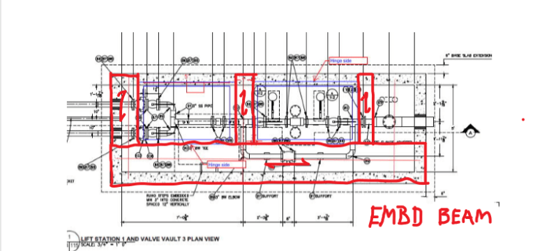
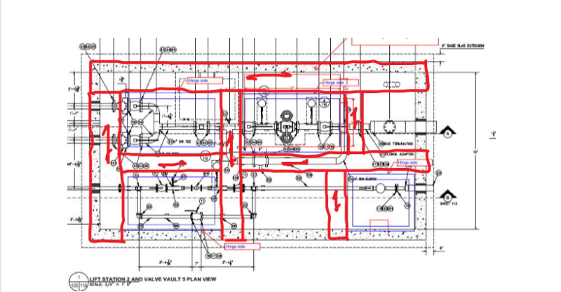
Our mechanical engineer sent a sketch of the proposed openings (see attached figures) and some of them concern me with how the load will be distributed around the openings. To simplify, I looked at it as beam segments in each direction around the opening. Then distributed the uniform live load. I am trying to avoid FEM. I am also concerned with the sections that would essentially cantilever from the wall to the edge of the opening. I assume I will need beams configured to support the top slab with the multiple openings. However, I feel like i have seen top slabs with multiple openings like this before.
Any thoughts on how you would approach this? Or am I over complicating this?
Thanks!
I am designing a cast-in-place rectangular valve vault structure. Owner requested CIP instead of precast. There are several structures with different dimensions (5'x10', 5' x 15', 10' x 20'). They are 6-feet deep. They will have a non-traffic live load (300 psf). We originally designed it as a one-way slab (10" thick) with one aluminum access hatch to enter the vault.
Now, the staff is asking for multiple hatches in the cover slab for the longer structures. The reasoning being they want to avoid entering a confined space as much as often. So with multiple hatches they can visually check valves and even reach down and operate them from the top slab if need be. They want off the shelf products (no custom hatches). So sizes of opening are based on Halliday product catalog.
Our mechanical engineer sent a sketch of the proposed openings (see attached figures) and some of them concern me with how the load will be distributed around the openings. To simplify, I looked at it as beam segments in each direction around the opening. Then distributed the uniform live load. I am trying to avoid FEM. I am also concerned with the sections that would essentially cantilever from the wall to the edge of the opening. I assume I will need beams configured to support the top slab with the multiple openings. However, I feel like i have seen top slabs with multiple openings like this before.
Any thoughts on how you would approach this? Or am I over complicating this?
Thanks!