Continue to Site

Eng-Tips is the largest engineering community on the Internet

Intelligent Work Forums for Engineering Professionals

  • Congratulations waross on being selected by the Eng-Tips community for having the most helpful posts in the forums last week. Way to Go!

Vaulted Window Wall Lateral Design

GaStruct

Structural
May 20, 2024
24
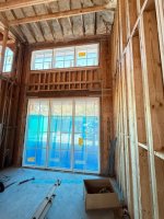
I have a 16' tall window wall where I initially specified 24" Simpson Strong-walls on each end. The wall widths were changed to ~12" in the field and the contractor installed this instead. See attached photo.

Installed is a (3) 11 7/8" LVL column on each side (other side not pictured) with straps at each header and (2) hold downs on the bottom. If you analyze this just as a cantilevered column system, then obviously the hold down reactions don't calc out to be adequate. I would like to look at this as a two-story portal frame type system but I am unsure how to keep the joints at the headers stiff enough.

Does anyone have any ideas for modifications to get this to work? Lateral load is small. About 2 kips total.

(Please ignore the hinge in the wall. That will be fixed.)
 

Attachments

  • window wall.JPG
    window wall.JPG
    133.1 KB · Views: 51
Replies continue below

Recommended for you

2k is a lot to deal with here. Any way to justify a 3 sided building model? Can't see you making this work easily without going back to the OG design.
Maybe adding some large red iron plate angley things screwed to the face of the beams.
 
3 sided open front could maybe work. The other sides are a vaulted hip roof so diaphragm discontinuity comes into play.

A plate connecting the headers to the column could work. They would need to fur the wall out though.
 
Chapter 14 of Malone's book covers a method of analysis for wood rigid frames, but... good luck. The time spent on analysis would be hard to justify.

I imagine you consider the entire depth of wall between the windows as a deep flexural beam that could be quite stiff, especially if you sheath the interior as well. Whether it's enough is hard to say. The skinny columns are the limiting factor I think.
 

bones206

The time spent on analysis would be hard to justify.
Couldn't agree more. I get tons of residences with crazy amounts of glass and my fee is never enough to justify a complex analysis that would require special detailing.

bones206

I imagine you consider the entire depth of wall between the windows as a deep flexural beam
Not quite sure I follow how the load gets resolved looking at the wall segment as a beam. Also, the load comes in at the top plate
 
Sorry, I'll try to clarify. I was idealizing the wall as a 2-story rigid frame, with a shallow top beam at the roof and deep middle beam between the windows. I imagine the deep middle beam would attract most of the lateral load due to it's flexural stiffness relative the the rest of the rigid frame members.

Getting the beam end moments into the column/wall segments is resolved through careful detailing of the "panel zone", as Malone calls it. I've never tried to do this myself, so I don't have a good feel for feasibility in this case. When I first read that book a few years ago, I got to that chapter and said "nope!"

By the way, anyone have the new 2nd edition? The price came way down so I was considering getting it if it's a worthwhile investment.
 
Disclaimer: I haven't actually designed such a thing for a real project, and although I have Malone's book, I also haven't read the chapter you're referring to.

Anyway, for my own curiosity, I created a quick rigid frame model of what you've described (using some assumed dimensions where they're not provided). I modeled all 4 members as a triple 11 7/8" LVL. Based on that, I arrived at end moments for the middle beam of about 6.7 kips. In terms of resisting this moment, you have direct bearing between the wood members (compression) and the metal strap (tension). Assuming a moment arm of 9", the resulting tension and compression forces are about 8.9 kips. Therefore, the metal strap connection would need to resist this force in tension and the vertical member would also need to resist the same force in bearing (compression perp. to grain being the limiting state).

I'll take a wild guess that the thin (Simpson?) straps in the picture have no chance of resisting this 8.9 k force. I think you'd need something closer to double 1/4" steel plates (one along each side) with maybe 4 or 5 1/2" diameter thru bolts into the vertical member and maybe 3 or 4 into the header. If this is roughly accurate, there's probably not enough width in the vertical piece to fit this many bolts while respecting the required end distances and spacings. At that point, the solution might need to be more like a 1/4" steel saddle wrapping around the three sides of the vertical member with direct bearing on the end.

Of course, even if you get all this to calc. out, some people would still say there would be excessive deformation in the wood under these forces. Considering this, an alternative option may be along the lines of threaded rods and hold-down connectors with the threaded rods being pre-tensioned.
 
I was thinking the middle beam would be the full sheathed depth between windows. Looks like maybe 3 ft deep.
 
Appreciate the replies all. I think I need to sharpen the pencil and get the loads down. Off to ASCE wind equations I go. The total load was 2k so it's 1k per side and I can get that down if I don't use the simplified method and tables with my conservative rounding. Then I'll share the load between the three moment connections at the two beams and base. Hopefully I can get a reasonable couple that can be handled with straps at the beam and won't rip out at the foundation.

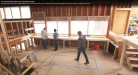
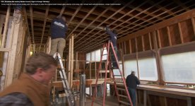
Side note.... I was watching This Old House the other day where they did a modern house form the 60's and saw a bunch of huge window walls with no visible consideration for lateral loads in-plane or out-of-plane. You can see an example attached here. Engineering just seems fake in residential construction when things like this have been standing for decades.
 

Attachments

  • TOH.JPG
    TOH.JPG
    221.5 KB · Views: 11
Here is better view. Glass along the entire length!
 

Attachments

  • TOH2.JPG
    TOH2.JPG
    208.7 KB · Views: 10
Side note.... I was watching This Old House the other day where they did a modern house form the 60's and saw a bunch of huge window walls with no visible consideration for lateral loads in-plane or out-of-plane. You can see an example attached here. Engineering just seems fake in residential construction when things like this have been standing for decades.
I am surprised how many modernist homes in my area don't have issues from the large expanses of glass. They have tons of other issues from floor system cantilever sagging to rot but that is another story. Don't stick your neck out too far on this project. It is the GC's problem.
 
Side note.... I was watching This Old House the other day where they did a modern house form the 60's and saw a bunch of huge window walls with no visible consideration for lateral loads in-plane or out-of-plan
Per my experience, most engineers nowadays aren't accounting for these things. I know there's a tendency for wood structures to hold together (somehow), but I like to provide a reasonable load path that I'm confident will work and that I could defend.

Not to go off on a tangent (again) but this can obviously be challenging when you have a client that isn't used to seeing designs accounting for this. I've sometimes felt like I'm trying to argue why I'm right and everybody else is wrong, while simultaneously entertaining my own self doubt. Maybe, I'm thinking, they did account for these wind forces, etc. and I'm just missing something. More often than not, though, when I've taken a closer look, I usually find these things were simply disregarded completely. If I'm told that engineer X does it this way, I'll often try to get a hold of their plans if I can and even offer to discuss the design with them. It seems this offer is often declined.
 
I will also add (to our collective defense), that I've been involved in at least a couple projects where large window walls did in fact fail. I want to say that in both cases, there were wind gusts around 70 mph that caused the failures. This is also well below the design wind speed in my estimation.
 
I have nothing to add besides how I love "large plate red iron angley things" that's got to be the next classic right after "you are in a twisty little maze of passages, all alike."
 

Part and Inventory Search

Sponsor