As pointed out in the old thread below, it's sort a norm to use 1/3 octave band for environment vibration assessment.
"One-Third-Octaves for Dummies"
Link
The bandwidth increases as central frequency so spectral leakage in high frequency band (>20Hz)is not a concern.
But then it come to very low frequency, this become a serious issue since the bandwidth is so narrow any spectral leakage will distort the picture.
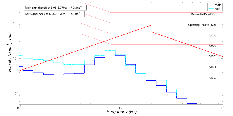
For example, we can see the stairs from very low frequency (<3Hz),and they might be a leakage from a very low frequency (1Hz).
1/3 Octave Band, Main Signal and Ref Signal

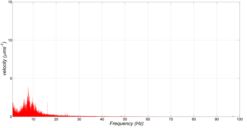
Main Signal FFT

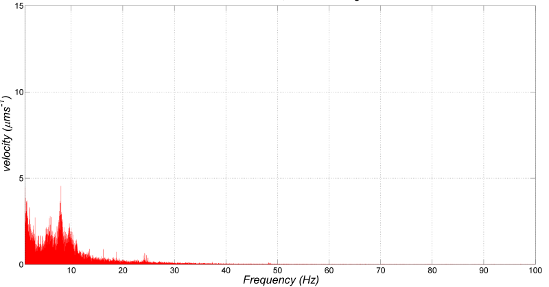
Ref Signal FFT

For a normal vibration control, we don't care much about very low frequency area (like the VC-B criterion, the limit went up at very low frequency) and part of the reason is that very low frequency excitation is hard to be isolated. However, for a very stringent vibration control zone, very low frequency is of paramount consideration. My question is how do we distinguish spectral leakage from actual environment noise, and eliminate it, especially at very low frequency bands?
I have thought of windowing, but someone told me that for environment vibration assessment we shall not use other than rectangular window in order not to distort actual environment noise.
"One-Third-Octaves for Dummies"
Link
The bandwidth increases as central frequency so spectral leakage in high frequency band (>20Hz)is not a concern.
But then it come to very low frequency, this become a serious issue since the bandwidth is so narrow any spectral leakage will distort the picture.
For example, we can see the stairs from very low frequency (<3Hz),and they might be a leakage from a very low frequency (1Hz).
1/3 Octave Band, Main Signal and Ref Signal

Main Signal FFT

Ref Signal FFT

For a normal vibration control, we don't care much about very low frequency area (like the VC-B criterion, the limit went up at very low frequency) and part of the reason is that very low frequency excitation is hard to be isolated. However, for a very stringent vibration control zone, very low frequency is of paramount consideration. My question is how do we distinguish spectral leakage from actual environment noise, and eliminate it, especially at very low frequency bands?
I have thought of windowing, but someone told me that for environment vibration assessment we shall not use other than rectangular window in order not to distort actual environment noise.
