Continue to Site

Eng-Tips is the largest engineering community on the Internet

Intelligent Work Forums for Engineering Professionals

  • Congratulations KootK on being selected by the Eng-Tips community for having the most helpful posts in the forums last week. Way to Go!

VFD High Input Current 1

Status
Not open for further replies.

MitchusMaximus

Electrical
Jan 25, 2023
16
Hi everyone, I've got a customer who set up a TechTop TD350-011G-2 VFD for a 15HP pump application. On a whim he measured the input current, and measured 60-62 Amps. This is about 20 Amps higher than the VFD's rated input current, and he measured this range on all three input phases, which tells me there isn't a phase failure. The motor's FLA is 38 amps at 230V, and the output was measuring around 44.5 Amps on all three phases. I've been fighting to get to the bottom of why this reading is so high, but am coming up empty. TechTop's engineers recommend adding a line reactor in case the harmonics are causing this high current, but I am doubtful that's going to solve the problem. I'll detail the measurements and what we've tried:

VFD's rated input current is 43A and output is rated 42A
Input voltages are measuring 123V from line to ground, and 210V from phase to phase. By all accounts the power seems well balanced.
When the drive is running the motor, VFD output is measuring 44.5A, input 60-64A.
Carrier Frequency is set to 2KHz
In addition to clamp ammeter, we looked at a parameter displaying the input current while the motor was running, and it read over 70Amps. The meter being used is a Fluke 323 True RMS, which I don't think has low-pass filters for accurately measuring VFDs, but I would imagine that the internal measurements of the drive itself would be more accurate.
When the motor is hooked up to a bypass contactor, the current drawn measures about 42-43A.

At first it seems like these are the currents the drive would pull if it was running off single phase power, but the measurements my guy has taken seem to demonstrate that all three phases are providing power. Further, if the drive really was drawing 50% more amps than rated, I would have expected the input diodes to have blown up pretty much immediately. Best case scenario is that the measurement tools are not accurate, or maybe the pump motor is undersized for the job it is trying to do. I am kind of out of ideas at this point, and if any of you have some insight, I'd appreciate it.
Thanks,
MM
 
Replies continue below

Recommended for you

You have to take into account power factor and the difference between kVA and kW.
 
My first question would be how the current is being measured. Due to the high levels of harmonic distortion, especially on the output, a typical DMM can give misleading results. The best approach for the output current is to believe what the drive is telling you, rather than trying to measure it directly. For the input current, you would need a good quality True RMS meter. I would also check the motor to see how hot it is.
 
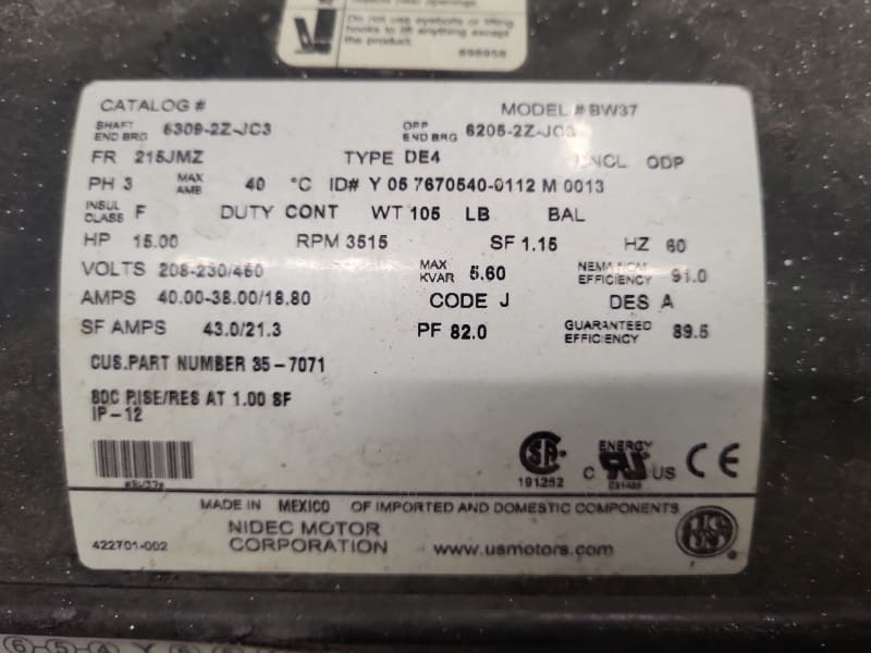
Here is a picture of the nameplate, for reference. It looks like the Power Factor of the motor is 82.0.
The current was being measured both with a clamp True RMS meter, but I'm not sure if it has the filtering required to get a proper measurement, and with a read only Input Current parameter on the drive itself.
If it really is just a problem with the measurements, that would be great. I think I would just need some good evidence to convince my customer that the drive is running properly, and the current method of measurement (no pun intended) is showing inaccurate readings.
IMG_20230622_093106_01_cqr41l.jpg
 
Did I miss it?
I don't see what frequency/RPM you are running at.
But.
When the drive is running the motor, VFD output is measuring 44.5A
Motor SF Amps; 43 Amps
VFD's rated input current is 43A and output is rated 42A
When the motor is hooked up to a bypass contactor, the current drawn measures about 42-43A
Try either dropping the speed a couple of RPM/Hz (About 2% for a centrifugal pump. About 3.5% or 4% for a positive displacement pump.)
Or
Throttling the discharge slightly (If this is a centrifugal pump.)
I would trust the VFD reported Amps.
One of our departed Gurus had an issue with some of Fluke's algorithms.
You are pushing the motor and VFD a little over 100%
As for the suspect readings, I suggest a different meter as a first explanation.

--------------------
Ohm's law
Not just a good idea;
It's the LAW!
 
I forgot to mention the frequency output, I believe it is being run full speed at 60Hz. Bringing the speed down should reduce the output current, I wonder if it would be able to bring the input reading down to normal levels.
 
If you bring the output current down to 40 Amps (per VFD) that gets you out of the service factor and within the VFD rating.
But;
The input current is puzzling.
There may be something open internally and the drive may be single phasing due to an internal fault.

--------------------
Ohm's law
Not just a good idea;
It's the LAW!
 
My guess: they have a cheap meter that is incapable of accurately reading the high harmonic current as separate from the active current doing the work through the drive.


" We are all here on earth to help others; what on earth the others are here for I don't know." -- W. H. Auden
 
It makes sense to me that even the True RMS Fluke 323 meter would not be able to distinguish harmonic current from actual current drawn by the drive, but does it make sense that the parameter displaying the input current on the drive itself would also show such a high current without accounting for the harmonics? I suppose if it brings the price of the drive down by not including the filters, it makes a bit of sense.
Thank you for the input, you guys.
 
Looks to me like you're running the pump and motor at just over 100% of rated power so it's all getting rather marginal.

however that large a discrepancy between input and output power can only really be a measurement one otherwise where is all that power going? Your VFD unit would be putting out ~4-5 kW if was being lost inside the cabinet so you must be able to notice that amount of heat coming off the unit? Or not?

Have you measured line voltage in?

Remember - More details = better answers
Also: If you get a response it's polite to respond to it.
 
We measured the line voltage at 123V from each phase to ground, and 210V between phases. The voltage was pretty good and even between phases. I don't think my customer has let the drive run long enough to tell if the drive gets extremely hot when he saw the input current measurement, but 4-5kW would produce lots of heat FAST, right? The drive is wall mounted, so it won't become an oven, but that would still be a pretty large amount of heat coming off, I imagine.
 
Motor is overloaded by 7-8%.
Need to reduce VFD output frequency.

Check / measure DC bus capacitance value.
I think is low (not enough for full load / even some overload)and there are high input line spike currents, so a very low power factor.
If VFD has connectors to add a DC reactor may solve partial/total this issue.
 
As an aside to the issue of the motor being overloaded. Even if the motor nameplate says it has a 1.15SF, motor manufacturers will ALSO tell you that when run from an inverter, the SF is 1.0. In other words the motor is ALREADY having to deal with excess heat due to the harmonics, so you cannot ALSO burden it with being run into the SF. That will have little to do with the purported input current discrepancy though, it's more of a warning on how it is being used.

MitchusMaximus said:
...but does it make sense that the parameter displaying the input current on the drive itself would also show such a high current without accounting for the harmonics?
I don't know of any standard (as opposed to Active Front End) drives under around 400HP that show you the input current. If they do, it would likely be calculated off of the DC bus current, not measured on the AC input to the rectifier. It costs a lot of money (from the standpoint of making a VFD) and internal real estate to add the ability to read input current yet most standard 6 pulse wall mount drives don't need to do that. AFE, larger drives and those that can be paralleled to MAKE larger drives need to have input current measurement, but not typically a drive in the 15HP region.


" We are all here on earth to help others; what on earth the others are here for I don't know." -- W. H. Auden
 
If you have access to a scope or a power analyzer that could really help provide more details on what is going on.

Casey

 
Status
Not open for further replies.

Part and Inventory Search

Sponsor