MitchusMaximus
Electrical
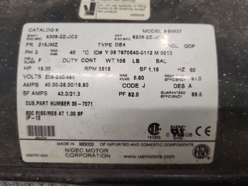
Hi everyone, I've got a customer who set up a TechTop TD350-011G-2 VFD for a 15HP pump application. On a whim he measured the input current, and measured 60-62 Amps. This is about 20 Amps higher than the VFD's rated input current, and he measured this range on all three input phases, which tells me there isn't a phase failure. The motor's FLA is 38 amps at 230V, and the output was measuring around 44.5 Amps on all three phases. I've been fighting to get to the bottom of why this reading is so high, but am coming up empty. TechTop's engineers recommend adding a line reactor in case the harmonics are causing this high current, but I am doubtful that's going to solve the problem. I'll detail the measurements and what we've tried:
VFD's rated input current is 43A and output is rated 42A
Input voltages are measuring 123V from line to ground, and 210V from phase to phase. By all accounts the power seems well balanced.
When the drive is running the motor, VFD output is measuring 44.5A, input 60-64A.
Carrier Frequency is set to 2KHz
In addition to clamp ammeter, we looked at a parameter displaying the input current while the motor was running, and it read over 70Amps. The meter being used is a Fluke 323 True RMS, which I don't think has low-pass filters for accurately measuring VFDs, but I would imagine that the internal measurements of the drive itself would be more accurate.
When the motor is hooked up to a bypass contactor, the current drawn measures about 42-43A.
At first it seems like these are the currents the drive would pull if it was running off single phase power, but the measurements my guy has taken seem to demonstrate that all three phases are providing power. Further, if the drive really was drawing 50% more amps than rated, I would have expected the input diodes to have blown up pretty much immediately. Best case scenario is that the measurement tools are not accurate, or maybe the pump motor is undersized for the job it is trying to do. I am kind of out of ideas at this point, and if any of you have some insight, I'd appreciate it.
Thanks,
MM

