Continue to Site

Eng-Tips is the largest engineering community on the Internet

Intelligent Work Forums for Engineering Professionals

  • Congratulations MintJulep on being selected by the Eng-Tips community for having the most helpful posts in the forums last week. Way to Go!

VFD power cable shielding (screening) issues 1

Status
Not open for further replies.

jraef

Electrical
May 29, 2002
11,342
I have been heavily promoting the use of VFD shielded power cable in my installations, and most of the problems I have experienced in the past have been diminishing to near extinction. But today, I went to a site with MULTIPLE motor failures connected to a VFD system that I designed, but was altered before purchase and installed by neanderthals. So in my investigation, I found that ALL of the repeated motor failures are happening in the exact same type of application, wherein they took the one single drive I had put into an MCC, and used it to run 4 smaller motors (12A drive running 4 motors that are 2.7A each) on evaporator coils in a cold room. The motors are supposedly "inverter duty" (but I find that is often about as reliable as a fox telling the farmer that the chickens are safe), I could not see the actual motors. So at first glance it SHOULD have been OK in theory. They did install a Load Reactor on each drive, then they used VFD shielded cable, one that has 3 power leads, 3 symmetrical ground leads nested in them, an overall braided shield over those 6 and a separate EGC (Electrical Grounding Conductor, a term used in the US similar to a "PE" conductor). The typical linear distance from MCC to evaporator set is between 300 and 400 ft, through open cable tray. The VFDs did not show faults in the fault logs, other than Power Loss faults typical of being powered down from opening the MCC cubicle doors.

The only big problem I can find with the installation is that the neanderthal electricians just routed the cables haphazardly (as in a bowl of spaghetti) in cable tray along with other full voltage motor leads and the incoming power leads, and then when they ran the shielded cable to the motors, they cut and taped off the shields at the motor connection box end, so they are shielded only at the VFD end. The motor lead cable goes from the MCC to a fiberglass box on the side of each evaporator, and inside is a local disconnect switch, a power splitter block, and a ground bar, to which the EGC is attached, along with 14ga ground wires from the motors. Motor leads from this box to the motors themselves are NOT shielded any longer, they used what appears to be non-shielded flexible wire through gland fittings on the box. I always tell people to ground both ends of shields on POWER cables, because the intent is to form a sort of Faraday cage. But what does / could happen if only one end is grounded? Could this possibly explain the multiple motor failures?

More relevant info:
(1) The motor re-winder that has repaired these has told the user that the motors are failing on "single phasing", which makes no sense to me. The VFDs in question should trip out on loss (or severe imbalance) of output phase current. I have provided the end user with EASA photos of typical single phase motor failures and typical turn-to-turn insulation failures due to standing waves, they have yet to share that with the re-winder to confirm his findings.

(2) To my horror, the user deliberately CHOSE to remove the separate Manual Motor Starters at the evaporators which were to be protecting the individual motors. So there is NO realistic motor overload protection for these 2.7A motors, other than the OL setting of the VFD, which is set at 10.8A. I have told my contact on the job site that this violates the NEC, but the decision came from a manager, so he said he does not want to challenge him and has asked that my report de-emphasize that issue (not likely). Still, these are evaporator coil fans, it is virtually impossible to overload them, and they are only 3 months old so no time for normal bearing wear. While I was there today the VFDs were at 55-60Hz and the 4 motors were drawing only 4.5 - 4.8A collectively for all 4 motors.

My theories at this point are:
1) The lack of shield grounding at one end rendered the shield ineffective, so standing wave generation caused first-turn insulation failure, which the motor re-winder was unfamiliar with and misidentified as single phase damage.

2) The lack of shielding is causing rapid bearing EDM damage and failure, which causes the motors to overload, which again, the re-winder misidentified as damage from single phasing.

3) None of this has any importance whatsoever, and all of it was just caused by the neanderthals who did the motor hookups likely not making good connections at the splitter blocks. Still, I would have expected the VFD to trip on that though.

Please share your thoughts.

"Will work for (the memory of) salami"
 
Replies continue below

Recommended for you

Yes, they usually run them from a multi-tap transformer. So they are used to sine-waves.

I can't wait to hear from Jeff what make his motors are.

Gunnar Englund
--------------------------------------
Half full - Half empty? I don't mind. It's what in it that counts.
 
Don't forget the obvious too; be from Missouri: prove it yourself that all output connections are tight. With all those cables and motors, one single loose phase connection that comes and goes on one single phase of one single motor in the group can generate super huge spikes that take out motors in minutes, irregardless of load.

 
mikekilroy said:
Consider a 1:1 isolating transformer in place of the reactor. NOT! If this were on 50 or 60hz INPUT to vfd side, fine, but NOT on output. You CAN use autofmr on output as we have done may times, but the reason is to change the vfd vs motor voltage - not an issue here.....


Have you ever tried it? I only did limited testing, but the results I got showed that a delta-wye transformer will provide a sinewave output voltage without the issues a sinewave output filter can introduce as mentioned by Marke. Also, it's much simpler then a sinewave filter with no capacitors so it's less likely to fail.
 
We never tried an iso xfmr on output as jobs we do typically require variable speed from 0 to 2-8x base speed. So an iso xfmr would not work out of the box since it won't pass current at such low fundemental freqs (below 50-60hz). Now a job that requires only say 40-60hz operation, that would be interesting to try. Wonder if the drive would START the motor from a rest tho without faults... In fiddling around, I did try an iso xfmr on output of a 10hp 230v vfd but could never get past around 5hz output before faults; could have been my xfmr was not good match tho....

 
So an iso xfmr would not work out of the box since it won't pass current at such low fundemental freqs (below 50-60hz)

Why not? Stay within the V/Hz ratio of the transformer and it will work fine as the frequency varies. You need to ensure that any voltage boost (either due to the fixed V/Hz drive programming or the automatic flux vector operation) doesn't saturate the transformer.

 
Pictures:

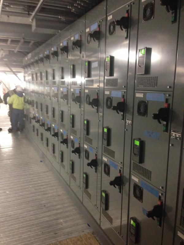
Overall MCC installation.
IMG_0319.jpg


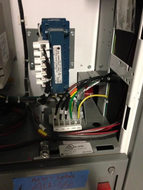
One of the buckets with a single VFD feeding 4 motors. Notice that shield is terminated separately from EGC.
IMG_0312.jpg


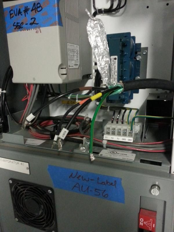
Terminations removed to show more detail. the cable has a braided shiled in addition to the foil, but they cut the braid, twisted the foil and terminated it...
IMG_0321.jpg


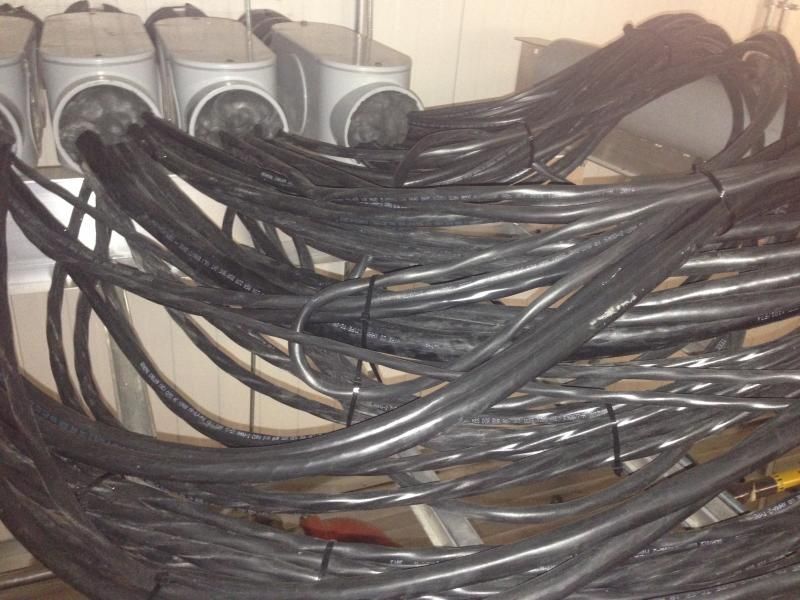
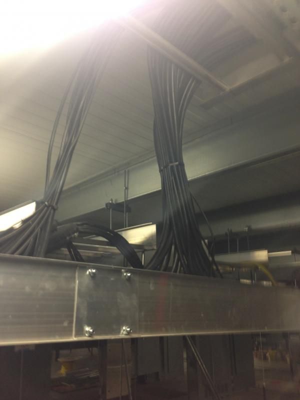
Cable routing to tray. These are not "VFD" cables, they are just shielded tray cable.
IMG_0314.jpg


Spaghetti bowl routing through a wall penetration. No attention to noise abatement procedures (not to mention professionalism).
IMG_0318.jpg


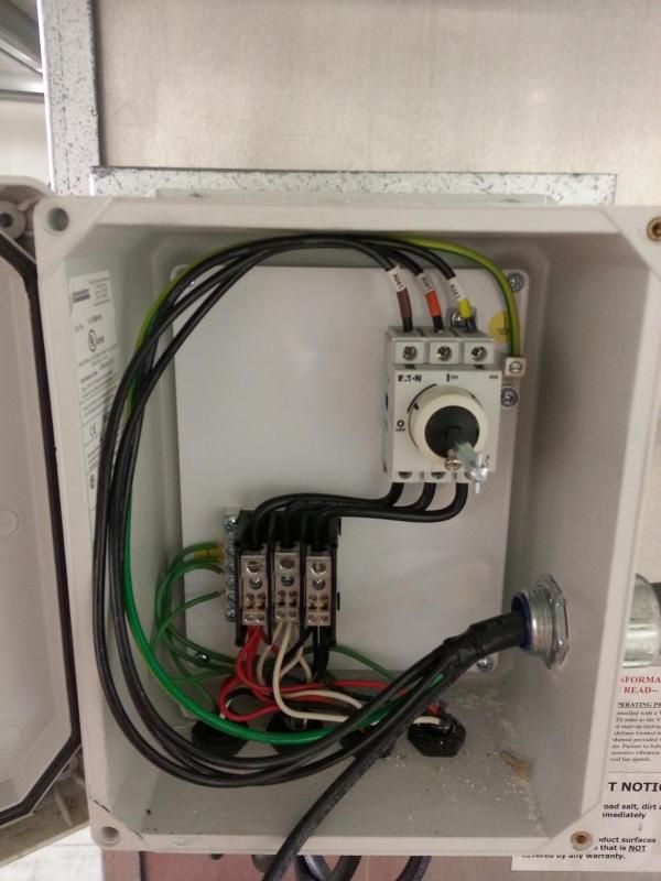
Junction box / common disconnect at Evaporator end (where the motors are). Shield is just cut off at this end, not connected to anything. EGC terminates on the ground lug next to the disconnect, but the remainder of the ground wires are only connected to it via the enclosure back panel.
IMG_0324.jpg


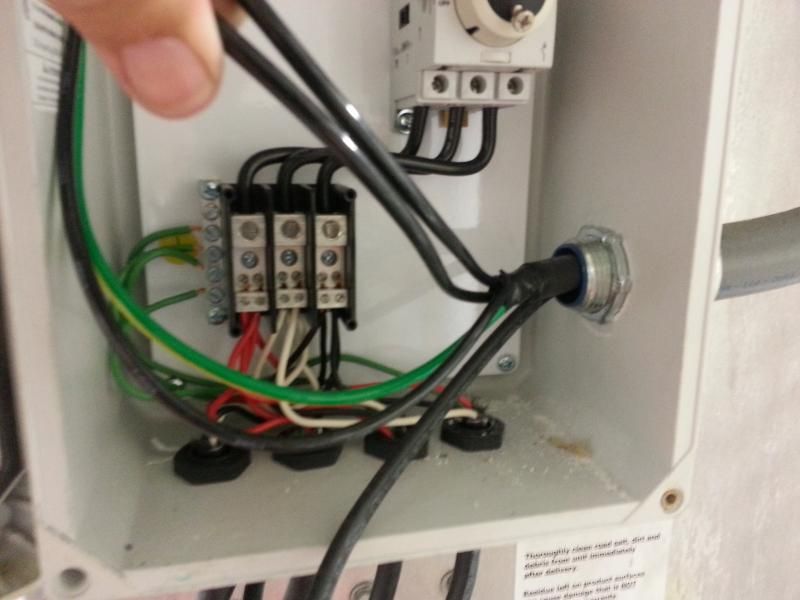
Detail showing that the cables exiting this box going to the individual motors are just using flex cord through cord grips, no more shielding.
IMG_0323.jpg


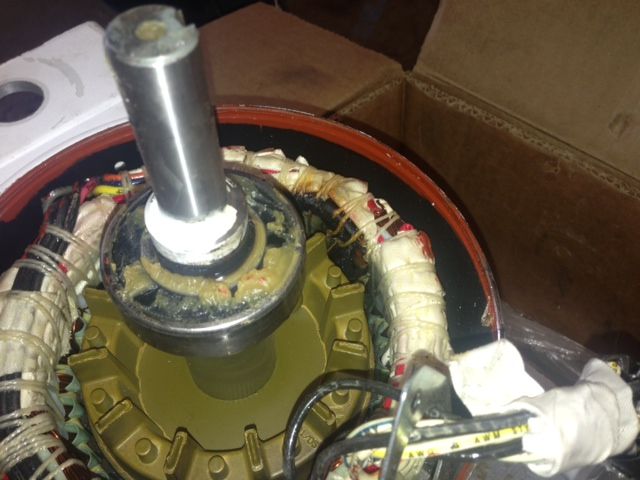
Photo from the motor shop, showing what they claim is 'single phasing" damage to the winding. I believe this looks more like damage due to standing wave insulation breakdown, at roughly about 2 o'clock.
IMG_0322.jpg


They are claiming that the while taped device in this photo is the embedded thermal protector for the motor, hence they do not need individual motor overload relays. If it really is a 3 pole "klixon" device opening the Wye point of the motor windings, then they would be correct in that code assessment, but I'm not convinced until I see data sheets on the motor. It's possible, but it's also possible that this is just a thermistor connection, and they ASSUMED it would be OK, but in fact is completely useless without being connected to a Thermistor Relay somewhere that would then tell the VFD to shut down. Still waiting on details of that.


"Will work for (the memory of) salami"
 
Only in that they sent me the motor nameplate data and it is indeed a 3 phase motor with an internal thermal protection switch that opens at 140 degrees, which qualifies in lieu of external OL relays. But that basically also confirms my assessment that the damage seen in the winding is NOT from single phasing, but rather from insulation breakdown.

"Will work for (the memory of) salami"
 
Jeff

No restrictions when it comes to PWM? Like for the Ziehl-Abegg ones?

I still haven't got a clear picture of the cabling. Are all motor cables run from the inverter? With one cable for each motor?

Or is there one cable running from inverter to junction box and then separate cables running from junction box to motors? See 17 Jun 14 23:44.


Gunnar Englund
--------------------------------------
Half full - Half empty? I don't mind. It's what in it that counts.
 
Looking at the pictures, the motor does not look like a "fan motor" with a high slip rotor as I am used to.
The length of the cables to each motor 300ft to 400ft is around the length that could cause transient voltage amplitudes to double.

The interesting thing to find out, is if the breakdown is first turn phase to phase, or phase to earth, or center winding shorted turn or similar.

Do you have a maximum insulation voltage rating for the motors?

We commonly use a single VFD, around 4KW, to supply up to 4 motors on the output with neutral screened cable and average cable length of 60M per motor. We add a manual motor starter at the VFD end of each cable to provide the individual motor protection. - never had a problem.

As a thought, I wonder what would happen if the thermal switch opened a few times while it was running on the output of the VFD and that length of cable. Would it produce some very high inter winding voltages at the switch end? I would expect so. Once again, an indication of where the breakdown was may give a clue, but here, it is very hard to get sensible information from the motor rewinders. I have to go and look myself because every failure of a motor on a drive is reported as "first turn failure" even when the windings are 100%.

Best regards,
Mark.

Mark Empson
Advanced Motor Control Ltd
 
Mark,
The more I think about your last statement, the more it makes sense. Whenever I tell people not to open a contactor down stream of a VFD, they ask why and I explain how the arc formed in the separating contacts acts as a capacitor tank circuit tht increases the voltage until the dielectric of the gap finally stops the current flow, and that dV/dt will eventually damage the transistors. But I never thought through the effect that might have on the motor windings and although I have never seen that, it may be because the transistors fail first. In this case it may be that because the VFD is protected from that dV/dt by the load reactor the effect is moved down to the windings, or at least maybe exacerbating any reflected wave spike action also taking place.

New info that may also be interesting. My employer recently bought a small company that makes power quality equipment, most famous for having a voltage sag ride-through device that does not rely on batteries or capacitors. As part of their sales efforts, they created an on-line power quality meter that, if enabled, allows users to access its records of line power anomalies. As it so happens, there is a nearby customer (less than a half mile away) that has one installed and is web enabled, so on Monday my product manager for that system is going to check the reports for the window of time in which the latest failures happened, since we know they happened between when I left and the following morning. That may be interesting as well, either to see if there was something, or even to eliminate that possibility.

I'm writing my report this weekend, in which I am going to tell them that without much more thorough analysis by someone who can spend sigificant time on site and work live with proper metering equipment, the best I can offer up are theories and possibilities. But I'm going to lean on this being insulation failure due to high voltage spikes caused most likely by the reflected wave phenomenon exacerbated by installation problems and possibly other factors. I'll wait for that other report before I send it of course, but I just can't help but stay focussed on this as the issue. I think it is too many failures to be loose connections, nobody is THAT bad, and the damage evidence I see in that motor photo does not point in that direction, or to sustained overload conditions.

"Will work for (the memory of) salami"
 
Hi Jeff

It appears that the common denominator seems to be time related. If I understand you correctly, you seem to get multiple failures rather than just one randomly.
If it is a winding to ground fault, then is it possible that there is a three phase supply problem where the three phases are moving together relative to ground and transient voltage exceeding the insulation to ground? This could be a combination of transient voltages from the VFD coinciding with transient voltages on the supply.
Many years ago, I found a problem, always the same your of the night, causing a bunch of VFDs to shut down on instantaneous overcurrent.
This was tracked down to power factor switching on the 33KV causing common mode transient voltages on the 33KV which were then capacitively coupled through the supply transformer and shifted the whole supply relative to ground. The capacitance to ground on the output of the VFD (Motor and cables) cause a current transient at the output of the VFD.
Fixed by replacing the corroded earth strap on the star of the transformer.

A severe brown out situation could cause current to rise and overloads to operate as another scenario, but that should be more obvious.

Best regards,
Mark.

Mark Empson
Advanced Motor Control Ltd
 
I explain how the arc formed in the separating contacts acts as a capacitor tank circuit tht increases the voltage until the dielectric of the gap finally stops the current flow, and that dV/dt will eventually damage the transistors. But I never thought through the effect that might have on the motor windings and although I have never seen that, it may be because the transistors fail first.

Jraef,I was sent to one of the large last remaining steel mills in Philli on such a case. For a month previous, the local motor repair folks, the OEM motor mfgr sent engineers, and no one found why 460v motors were failing anywhere from 5 MINUTES TO 3 HOURS - even under NO LOAD. About 20 motors failed during that time. Never once did the drive fail

I told the customer he had to have a loose wire on one of the motor phases. In my diagnostic process, I first added a motor inductor - no help; they lost 2 more motors in 1 day. Next we had the motors vacuum impregnated as we KNEW the fault was ozone eating the varnish causing shorts. No fix.

I finally went to the customer site. I found a loose screw on one motor phase at a terminal strip below this huge machine. Simply a loose screw. Result was in excess of 3000v spikes. Scoping the normal motor spikes showed about 1700v spikes; my motor designer assured me the insulation was good to 2500v; above that ozone would build up and in short order eat the varnish and short windings.

2 turns tightening on that screw and the motor has run ever since my trip in about 2000.

Don;t discount a possible loose connection in all those cables.

 
Ozone degradation is a slow process. If your motors fail in between 5 minutes and three hours - I can't think of ozone as the culprit. High voltages and insulation failure, yes. But ozone takes months or years.

Loose screws usually show in motor current and performance. And it shall be a hell of a loose screw to be able to produce even 1 kV peaks. Remember that a loose screw isn't the same as an air gap.

Also, if there is any current in a loose connection, you will have heat.

And, finally, there should (yes, I know about should and reality) be maintenance looking after loose screws. IR inspection is used for that.

Gunnar Englund
--------------------------------------
Half full - Half empty? I don't mind. It's what in it that counts.
 
Skogsurra, those were my thoughts exactly too - before I got into this particular case. I have since had multiple other cases that proved of ozone shorted motor windings in less than 1 hour, so empirically I know it is true.

That said, one can google 'how fast does ozone breakdown polymers' and find various studies that prove it can cause issues in much less than 1 hour. For example, take this study I just googled:


You can see in figure 1.11 that ozone in such small concentrations as 3ppm can cause cracks in polymers (typical wire varnish) in less than 2 hours; 23 minutes for some materials per figure 1.12.

But what about near 100% concentration? How long would THAT take to crack the insulation?

But irregardless of cracking, what if a wire is ALREADY NICKED from being hammered into its slot? It does not require this 23 minutes to crack; so if already exposed, is it not READY to short as soon as ozone builds up?

What is the resistance of ozone? I did not google it as my experience with DC motor commutators flashing over already proved to me many many years ago that ozone build up around a commutator makes for ZERO ohms and thus instant flames; I may be wrong but I doubt it.

I must admit that attempts to vacuum impregnate the stators DID extend the life of these motors from this one loose phase connection: from 5min or 2 hours - to a day or two. Reason seemed obvious at the time: No air pockets between windings inside the stator meant no O2 to chemically change to O3, so it took longer for the ozone to build up and cause cracks in the insulation.

I believe ozone can be miade from air in very short order. I did not research this, but assume from empirical data of seeing atom bombs split atoms in useconds it does happen quickly.

So as strange as it sounds on the surface, I stand by my empirical data that tells me a loose connection can cause motor insulation failure in as little as a few minutes.


We seem to have quite different experiences with Ozone. The already nicked wire - there I agree that it doesn't exactly improve the situation. :-(

Gunnar Englund
--------------------------------------
Half full - Half empty? I don't mind. It's what in it that counts.
 
If you're seeing >3000V spikes on the motor connections then you don't need to wait for ozone to cause insulation failure.
 
Well, I wrote a 14 page report and sent it today, complete with "27 8 x 10 glossy photographs with circles and arrows and a paragraph on the back of each one explaining what each one was." **
I think that by the time I was done I used pretty much everything mentioned in here to assign blame, then I might have ended up getting a bit carried away by including President Obama (a popular sport now), but recommending that they hire someone with REAL tools to go spend some time on site and investigate this more deeply.

We'll see what happens next.

** For those too young to recognize it, that's an excerpt from the song "Alice's Restaurant".

"Will work for (the memory of) salami"
 
Flashback ! ! !

Guthrie's autobiographical incident that inspired "Alice's Restaurant" occurred in 1965 in western Massachusetts (anything west of Dedham is the frontier to a blueblooded Bostonian and Stockbridge is nearly on New York border) . Ten years later, in 1975, having been the discharged from long-suffering 'service' in the US army, I returned from Germany and landed in, what to me, was a foreign land, eastern Massachusetts (I'm a mid-western by birth and worldview).

I, like Mr. Guthrie, was charged with violating the sanctity of the town dump; specfically, illegally removing property, to wit, a Chevy 305 engine complete with bell housing. He was dumping, I was scavenging, both illegal in the Commonwealth.

I worked the incident to great advantage, being 20-something at the time and trolling the bars for feminine company. Any 20-something knew the Alice's Restaurant in 1975 and could sing the refrain; some lovely ladies could even in harmonize.

Dan
 
Status
Not open for further replies.

Part and Inventory Search

Sponsor