Eng-Tips is the largest engineering community on the Internet

Intelligent Work Forums for Engineering Professionals

VFD Power Conservation

Status
Not open for further replies.

Jieve

Mechanical
Jul 16, 2011
130
0
0
US
I’ve been doing some voltage/current measurements on VFDs and have come across a peculiarity that I do not yet fully understand. The specific VFD I’m working with at the moment is a 2hp drive powered by single-phase (240V), with output to a 3-phase 2hp (230V) motor. I’ve looked at both current and voltage waveforms with a scope, input and output, and am trying to reconcile what seems to be a significantly higher apparent output power than apparent input power (kVA).

Looking at the VFD panel for example, at 3000 rpm I read 185.5 Vrms and 2.1 Arms. This gives an apparent power of 1.732 x 185.5 V x 2.1 A = 674.7 VA. At the drive input, using a Fluke 87V meter, I get 241.2 Vrms and 1.15 Arms. This gives 241.2V x 1.15 A = 277.38 VA. And the operator screen and fan use an additional 162mA that I haven’t subtracted out.

In this case the motor is unloaded, so current is basically the magnetizing current.

I was always under the impression that power in = power out, and that this held for apparent power as well as real power (I thought I had seen this with kVA in transformer calculations, as well as real power for power supplies). It seems that because the VFD is a power converter, somehow it’s not quite that simple. But then how does this play out in the VFD case? And is it only real power in = real power out? What about reactive power?

I appreciate any input.
 
Replies continue below

Recommended for you

So what you're saying is that real power is conserved but complex power is not. Which is not the case for a transformer, for example, where complex power is conserved. While not doing useful work, energy is still stored in inductors and capacitors, and must be conserved. So that doesn't quite explain what's going on.
 
VFD currents/voltage showed on own panel are not so precise especially at low values.
Output current are very away of sinusoidal, so even with an high accurate RMS device it's hard to extract RMS value of fundamental.
Also, output current harmonics are dependent of PWM carrier used/selected. Add to this rectifier input stage that feed output inverter.
 
If I am not mistaken your question boils down to can VFDs source reactive power, and the answer is yes they can. Inverters commonly are used as reactive power sources - consider a grid-tied batter that feeds a islanded system of reactive loads - source is DC (no reactive power in DC). Drives typically have a DC bus that feeds the inverter so would behave similarly.
 
iop95 said:
currents/voltage showed on own panel are not so precise especially at low values.

The motor power factor at full load is 0.9, giving sin(phi) = 0.4358, x FLA of 4.8 = 2.09A (magnetizing, unloaded current) which is pretty much exactly what the panel is reading.

iop95 said:
Output current are very away of sinusoidal, so even with an high accurate RMS device it's hard to extract RMS value of fundamental.

Do you mean input current? The output is pretty sinusoidal (albeit noisy), the input definitely is not. Which is where I thought the issue might be stemming from; reading of the input current accurately. I would think that a good true RMS meter would be able to measure it accurately though.
 
wcaseyharman said:
If I am not mistaken your question boils down to can VFDs source reactive power, and the answer is yes they can. Inverters commonly are used as reactive power sources - consider a grid-tied batter that feeds a islanded system of reactive loads - source is DC (no reactive power in DC). Drives typically have a DC bus that feeds the inverter so would behave similarly.

Right, they can source reactive power as part of the conversion process, but energy still needs to be conserved; that reactive power cannot come out of thin air. In my example above, the output VA is about 2.5x the input, that's the piece I seem to be missing.
 
Pure reactive power carries no energy, so yes, it can be sourced “out of thin air “ by active devices like inverters. Another example, STATCOMs, which are reactive power devices on utility system, have a single inverter and a DC bus, (like a VFD with no input). They source reactive power from essentially nothing (only clever firing of the IGBTs or whatever they are using to keep the DC bus voltage high). There are lots of other examples of similar equipment, but the bottom line is this - energy (KW) has to be conserved from input to output, but reactive power does not - the output side can source as much or as little as the load requires with minimal effect on the input.


wcaseyharman said:
Pure reactive power carries no energy, so yes, it can be sourced “out of thin air “ by active devices like inverters.

While I'm not familiar with STATCOMs, from a quick google search it seems that they have DC bus storage caps similar to a VFD. The energy to create the reactive power comes from the energy stored in the capacitors. So it's not out of thin air. And a particular DC bus cannot simply supply infinite reactive power, it's of course limited by the power input to charge those caps. The 2hp VFD I'm working with can't just generate 1000A of reactive current from the DC bus, for example. So there obviously has to be energy conservation taking place throughout its various forms.

wcaseyharman said:
If I am not mistaken your question boils down to can VFDs source reactive power, and the answer is yes they can.

I see your point, is that they can source reactive power from a non-reactive source. I think my question is actually more regarding the overall energy conservation. I see the energy going in and energy going out as described in my post, and am not following how the output can be much higher than the input. Some of that energy goes to charge the caps, but in the steady-state, it seems that the total power in should equal total power out.


By definition DC has no reactive power component, so in all case reactive power is generated at the inverter and does not “flow through” the device.

As a reminder,
Apparent power = SQRT(P^2 + Q^2)

If you agree that reactive power Q can be generated by an inverter, then it follows that apparent power, S, can be changed as reactive power is a component of apparent power.

Real power, however, follows the conservation of energy law, and whatever flows in the input must equal the output plus losses.
In summary:
Q = reactive power, can be generated
S = apparent power, can be changed due to changing reactive power
P = real power, cannot be created, input equals output plus losses.

So in your case, as waross mentioned, you’d see a small difference in real power across the VFD (losses), but apparent power can vary wildly depending on the reactive power to the load supplied by the VFD inverter.

Hopefully this makes sense, I’m not the best explainer.


Apparent Power = KVA

Real Power = KW = KVA x cos (φ)

Reactive Power = KVAR = KVA x sin(φ)

VFD output PF is low for unloaded motor

VFD input PF is high regardless of VFD output KW

Now do the math for both real powers.

And no, transformers cannot store energy (which is in KW-HR btw)


Muthu
 
wcaseyharman said:
Hopefully this makes sense, I’m not the best explainer.
Well I appreciate you chiming in and giving your input and spuring me to think about it more deeply.

wcaseyharman said:
By definition DC has no reactive power component, so in all case reactive power is generated at the inverter and does not “flow through” the device.

As a reminder,
Apparent power = SQRT(P^2 + Q^2)

If you agree that reactive power Q can be generated by an inverter, then it follows that apparent power, S, can be changed as reactive power is a component of apparent power.
All correct.
From my understanding, the reactive power at the output is just a result of the phase shift due to motor inductance when the IGBTs switch to generate the PWM voltage waveform. But no current would exist if there were no energy; the energy is taken in at the VFD input to charge the DC bus capacitors E = (1/2 C V^2), which is technically reactive power since there is a phase shift between voltage/current of 90 degrees when charging any pure capacitance. So to say there is no energy involved in reactive power is not entirely correct. Energy is converted and stored in the capacitors as an electric field or inductors as a magnetic field, and then ultimately converted to other forms. And energy is in the form of the magnetic field generated in the stator windings, which is partially reactive power, the rest of which goes to drive the motor to produce torque. It's true it doesn't dissipate as heat and does not directly generate useful work, but it still comes from somewhere; no energy can just be created from nothing. This is my reasoning for why I should be seeing equal total apparent power in and out of the drive, and why I'm having difficulty with the "only real power is conserved" and "reactive power can be created out of nothing" concepts. All energy needs to be conserved by the fundamental laws of physics.
 
Hmmm, I see there’s some confusion on some fundamental AC concepts.
The DC caps can’t have “reactive power” because the voltage on them is not oscillatory, reactive power is cause by the phase shift between a periodic voltage and current waveform.
I think you are getting hung up on the difference between energy and power transfer. Sure, energy is present with reactive power, but it’s not being transferred - the source is not providing anything, you can think that energy is just “sloshing” back and forth and only creating losses.
One last example that might help - I experience the phenomena you describe all the time. I test large machines as part of NERc required MOD standards, and we push and pull huge amounts of VARs - we can go from 100 amps to 2000 A on the generator bus and guess what - the fuel into the machine doesn’t change at all. So even with 10 times the current, the actual power, created by falling water or burning natural gas, doesn’t change, but the apparent power will go from 2MVA to 50MVA.

I’m not sure I can provide much more in a forum post, to provide a thorough explanation you are seeking would cover about half of a junior level power course in college, but suffice to say the issue with the VFD you are experiencing seems perfectly normal based on established electrical theory.

 
wcaseyharman said:
The DC caps can’t have “reactive power” because the voltage on them is not oscillatory, reactive power is cause by the phase shift between a periodic voltage and current waveform.
In the 3-phase rectified case you're correct about the voltage not really being oscillatory, in the 1-phase case though the voltage is a rectified single-phase sine wave so it is quite oscillatory. But you're correct about the reactive power in this VFD example; I was writing that thinking about the general case of connecting an AC source to a capacitor, and the voltage/current phase shift in charging and discharging that capacitor each AC cycle to illustrate the concept of energy transfer between source and capacitor via reactive power. However, in the VFD case that's not a great example, as the rectification process corrects the power factor.

wcaseyharman said:
I experience the phenomena you describe all the time. I test large machines as part of NERc required MOD standards, and we push and pull huge amounts of VARs - we can go from 100 amps to 2000 A on the generator bus and guess what - the fuel into the machine doesn’t change at all. So even with 10 times the current, the actual power, created by falling water or burning natural gas, doesn’t change, but the apparent power will go from 2MVA to 50MVA.
This is a great example illustrating the point, I will have to think about it a little more.

wcaseyharman said:
to provide a thorough explanation you are seeking would cover about half of a junior level power course in college,
Not sure that because I'm having an issue with this one concept, I would describe my understanding of electricity as that remedial. But this discussion has helped to provide some guidance into understanding what's going on a little better.
 
Jieve (Mechanical)(OP)9 Dec 23 07:09
" #1... VFD 3ph output ... 185.5 Vrms and 2.1 Arms, an apparent power of 1.732 x 185.5 V x 2.1 A = 674.7 VA. The drive 1ph input, 241.2 Vrms and 1.15 Arms. ... 241.2V x 1.15 A = 277.38 VA... The motor is unloaded. #2...I was always under the impression that power in = power out, and that this held for apparent power as well as real power".
You had already received numerous learned advice. I would like to add the following for your consideration.
1. With the voltage and current both taken with RMS values, the apparent power calculation in VA are in order.
1.1 Your concern/question is how can the VA[sub]out[/sub] > VA[sub]in[/sub] ?
2. For your case, Power in = Power out + losses*. Therefore, P[sub]in[/sub] > P[sub]out[/sub]. The difference is very small, as the losses* by VFD + unloaded motor are very low.
2.1 It is NOT true that VA[sub]in [/sub] shall be = VA[sub]out [/sub] .
3. Attention: Power = VA x pf = W
3.1 For your case, a) the pf[sub]in[/sub] is not equal to the pf[sub]out[/sub] .
b) the pf[sub]in[/sub] is say near to 1, where the pf out is < say 0.1 .
4. If you take the RMS value of voltage and current including pf into consideration, it would be clear that Pin > Pout.
4.1 However, VA out can be > VA in.
Che Kuan Yau (Singapore)
 
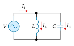
Let's see if you can do this basic math. I[sub]t[/sub] is bigger or smaller than I[sub]L[/sub] or I[sub]C[/sub]?

And again, energy and power are not the same. I am done.

qbnvoqfmjs88neputg82.png


Muthu
 
In a textbook I have here, "Fundamentals of Electric Circuits, 4th Ed" by Alexander and Sadiku, Chapter 11 discusses AC Power Analysis, with Chapter 11.7 entitled "Conservation of AC Power". In this section it discusses any network of various load impedances powered by an AC source and states "We conclude ... that whether the loads are connected in series or in parallel (or in general), the total power supplied by the source equals the total power delivered to the load. ... This means that the total complex power in a network is the sum of the complex powers of the individual components. (This is also true of real power and reactive power, but not true of apparent power). This expresses the principle of conservation of AC power ... From this we imply that the real (or reactive) power flow from sources in a network equals the real (or reactive) power flow into other elements in the network."

This states clearly that apparent power is not conserved, but its real and reactive components are. From this I'm sure one can understand the confusion;

A VFD is taking power in as real power and outputting complex power to a load, and one is being told that the reactive part of this complex power can generated out of nowhere, it seems to violate the conservation law stated above. So far, everyone has emphasized real power being conserved in this thread, but according to the above, reactive power should be conserved somehow in this as well, even if the VFD is acting as a power converter.
 
Jieve said:
[Do you mean input current? The output is pretty sinusoidal (albeit noisy), the input definitely is not. Which is where I thought the issue might be stemming from; reading of the input current accurately. I would think that a good true RMS meter would be able to measure it accurately though.]

Sorry, input current.
Output voltage also, it's away from sinusoid
As VFD is a non-linear load, need to use so called True Power Factor, that include THD factor.
 
You are wrongly applying AC theory about power flows in capacitors and inductors connected directly onto an AC source to a circuit with a rectifier and transistors.
 
In your case the VFD is the source of reactive power and the motor is the load absorbing the reactive power generated by the VFD inverter. Your reactive power is conserved, there’s no issue with the book or your VFD.
What the book is not emphasizing is it doesn’t take real energy to create reactive power, so generators, inverters, STATCOMS, even capacitors can generate reactive power without drawing real energy (ignoring losses)- hence the input of the VFD can have much lower apparent power than the output.
 
Status
Not open for further replies.
Back
Top