Eng-Tips is the largest engineering community on the Internet

Intelligent Work Forums for Engineering Professionals

  • Congratulations waross on being selected by the Tek-Tips community for having the most helpful posts in the forums last week. Way to Go!

Vortex breaker for pump suction in floating skimmer

Status
Not open for further replies.

MFJewell

Mechanical
Mar 2, 2017
366
0
0
US
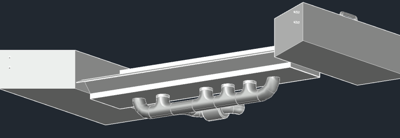
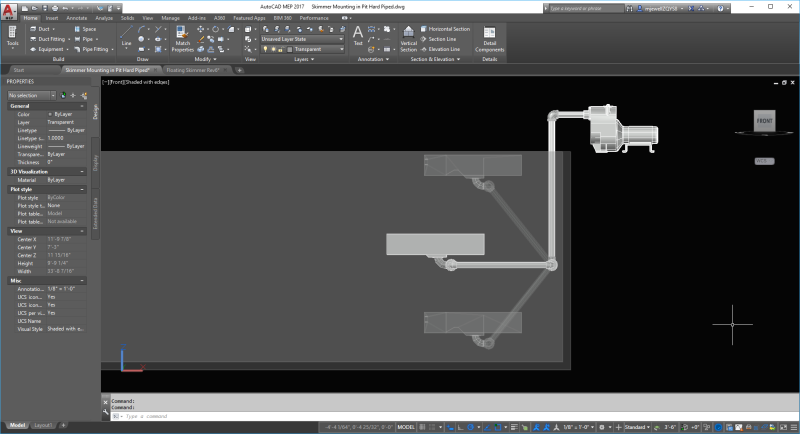
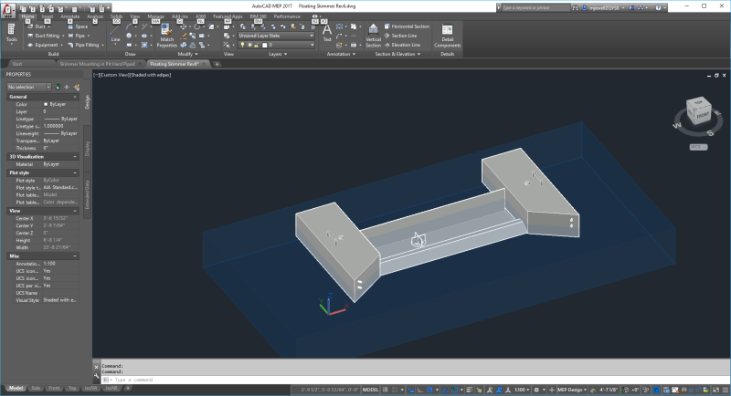
I am designing a floating skimmer that will draw off the top 1" of fluid in a pit. The skimmer has a sump that will hold ~4" of water (total volume of ~5 gallons). The suction line is connected to the bottom of the sump. The pump suction line is 2 inch schedule 40. My operating point on the pump curve with the pump I plan to use (using my estimated system curve) will be about 100 gpm. Using submergence rule, I should have ~6 feet of water to prevent air entrainment due to vortexing. I put a small vortex breaker at the suction line inlet, but have no experience with actual design of a vortex breaker, so I have concerns that I may still get air in the suction. I attached some images to show my current layout and design. CFD isn't an option to confirm the design. I've read some older threads on here and some articles online and think I have some basic direction I want to go. That said, anyone have any tips on avoiding air entrainment or vortex breaker design?

Edit: also want to add that the pit is open atmospheric and the fluid is water typically 70-95 degreeF.

Skimmer_in_pit_jlobdi.png
Skimmer_lgwzpr.png
 
Replies continue below

Recommended for you

I'm not sure 22 is correct. According to HI it is, but there are several other theories out there. As far as factor of safety, I don't really need any. This pit typically collects rain water. We have installed piping and valving from an adjacent pit so we can divert flow to this pit in the event of an oil spill inside the plant that gets in to the floor drains. From the discharge of the pump, it is piped to a sanitary sewer line. In the history of the plant (50 years), there has been 3 or 4 releases that required mitigation. So this system will sit mostly unused (unless operations wants to use it to drain rain water from the pit).

I have been exploring a smaller sump within the large sump and/or using a 6x2 reducer as the bell inlet as well. But if a simple vortex breaker will get me there, that is what I would prefer.
 
My bad - I meant 2"... corrected above, but take the points raised. Even if you only occasionally need it it still needs to work effectively.

a 6 x 2 bell reducer with top vortex breaker sounds good if you can't increase pipe size.

If the purpose is to skim the oil off the top why it is going to a sanitary sewer?? [just curious].

Remember - More details = better answers
Also: If you get a response it's polite to respond to it.
 
We are allowed per permit to discharge to city sanitary sewer. Our sanitary line is metered and monitored (prior to full discharge in the sewer), so we pay for whatever we send to them for treatment. Most of wastewater we treat on site and discharge to an adjacent waterway.

This is the transition piece I am considering:

sump_in_sump_venb4q.png

sump_in_sump_2_jtgvp6.png
 
Would think that the flow rate of 100 gpm is a bit arbitrary when this is planned for a potential spill cleanup.

The equipment that you plan to install will sit there unused and likely will not be in serviceable condition when it is needed.

Why don't you just contract with a firm like Safety Kleen that will come to the pit and vacuum up all of the oil when the actual spill occurs. Most likely, the oil will have to be sent off site anyway.
 
The 100 GPM is based on the potential inflow to the pit if we are diverting the plant drain system to it. Normal flow rate from the drains system is ~50 gpm, but if we are using more equipment, it will max around 100 gpm. Also, normal PM runs will be scheduled and operations may use the system to drain the pit of normal rain water accumulation.


A lot better IMHO. Just needs am anti vortex plate over that pipe and you're there. Could you put a pipe on the other side as well??

Remember - More details = better answers
Also: If you get a response it's polite to respond to it.
 
OP.yes there are many empirical rules available for submergence, however in your first post you clearly stated 6'of water to overcome air entrainment and vortex - in your case it is inches of submergence and your problem will be air entrainment.
Absolute minimum entry velocity is needed as is the maximum depth of water over the inlet. The modified inlet arrangement suggested is going in the right direction.
Simple demonstration of your system is to fill your kitchen sink full of water, pull the plug and watch what happens.

It is a capital mistake to theorise before one has data. Insensibly one begins to twist facts to suit theories, instead of theories to suit facts. (Sherlock Holmes - A Scandal in Bohemia.)
 
The sink analogy is only partially applicable. If I turned on the faucet and maintained a certain water level, I wouldn't get a vortex. In my skimmer, I will have a constant inflow as well that will allow it to maintain a level. Also a sink is bowl shaped, whereas my skimmer is flat bottom, sharp transition into the inlet(s).
 
Status
Not open for further replies.
Back
Top