Continue to Site

Eng-Tips is the largest engineering community on the Internet

Intelligent Work Forums for Engineering Professionals

  • Congratulations pierreick on being selected by the Eng-Tips community for having the most helpful posts in the forums last week. Way to Go!

Wall Designed As Strut & Tie 1

Status
Not open for further replies.

MDILY

Structural
Sep 18, 2020
5
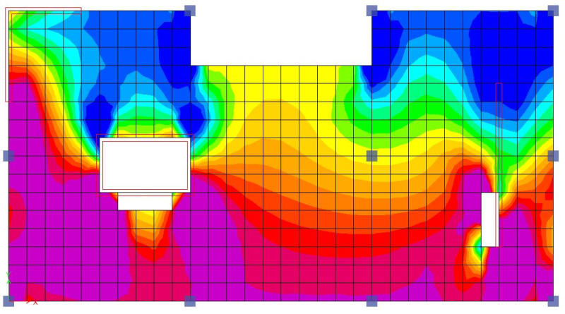
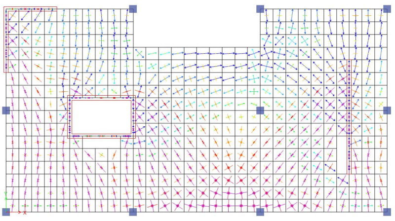
AS3600-2018 states that walls to be designed as strut and tie when H/L > 2. Can anyone walk me through how to design shear walls as strut & tie? Some examples will be great.
I understand how to design pile cap or deep wall (or beam) as strut and tie under gravity. But how do I design walls as strut & tie for lateral?
 
Replies continue below

Recommended for you

Interesting... so instead of a continuum of shells it uses a continuum of frames. It would be intriguing to do a side by side comparison, how much of the STM v FEA comes out in the wash when you vary the grillage/mesh size.

Do you have any worked (realistic) example of the pESA in action, Agent?

 
Do you have any worked (realistic) example of the pESA in action, Agent?

Trenno, meant to reply earlier. I'm not aware of any formal published examples from any industry bodies. The thesis on which it was based is available online from University of Canterbury, search for Debra Gardiner and pESA and it should turn up in google.

I did find this example of a seismic assessment that uses the method in searching for something. However, they used a really crude grillage (way too sparse to really tell where the loads are going in detail). But it may be useful, have only scanned through it and I'm not so sure it's that clearly setout in terms of the exact approach they took. Link
 
Thanks Agent,

I'm interested to see how this translates into the production engineering side of things.

I've come up with a basic example, which I would like to test using a 1m mesh/grillage size.

pESA_test_djtim1.jpg


pESA_loading_cmuzbm.jpg


Axial
pESA_struts_csgq6j.jpg


Axial F12
pESA_struts_F12_hoycte.jpg


Axial F11
pESA_struts_F11_a9xx01.jpg


Axial F22
pESA_struts_F22_h11tll.jpg


F12
pESA_F12_lauk8l.jpg


F11
pESA_F11_tbom6h.jpg


F22
pESA_F22_yzjmuz.jpg


FMax
pESA_Fmax_fiew7v.jpg
 
You'd apply your 1kN loads distributed to all the internal nodes, you're trying to represent the distribution of mass and hence diaphragm inertia. You wouldn't model walls and columns, just add reaction loads from your global pESA model to capture the transfer forces. Then run with some weak springs to restrain model in each degree of freedom at selected locations.
 
Agent666 said:
just add reaction loads from your global pESA model to capture the transfer forces
Is this in accordance with the capacity design approach though?
I see no reason why the approach wouldn't give the same results as FEA (in general)
 
The pESA loads are derived based on the overstrength of the building and or a minimum peak ground acceleration which usually governs in the lower levels. Each floor is looked at in isolation. You don't model floors in your global analysis using this approach.

The point is it is intended to result in an envelope of forces that captures the peak transfer and inertia forces within the diaphragm. A normal response spectrum or equivalent static analysis won't capture this. You'd otherwise need to do a time history analysis to get this information. The other benifit of doing it this way with existing structures you can tune the mesh location and also stiffness to capture the redistribution of loads or where the reinforcement for drag elements has been placed via an iterative approach. You cannot do this with a shell model, the load goes where the stiffness and mesh size says it goes. Generally extracting relevant information from a shell model is not easy, and you'll come across the issue of peak stresses at discontinuities not representing any actual loading or loadpath. A shell can also carry tension on the diagonal, there's no easy way to say a strut is a strut for example.

I'm not saying it's perfect, but it's the first codified approach we've had, before this people generally under designed diaphragms. There were a few diaphragm failures in our recent significant earthquake events leading to the development of the approach.
 
Thanks for an explanation, here's a star.
It sounds like an interesting procedure, I'll look into it for sure as I was always worried about diaphragm design.
Looks like pESA might solve a lot of insecurities.
 
Status
Not open for further replies.

Part and Inventory Search

Sponsor