Continue to Site

Eng-Tips is the largest engineering community on the Internet

Intelligent Work Forums for Engineering Professionals

  • Congratulations SSS148 on being selected by the Eng-Tips community for having the most helpful posts in the forums last week. Way to Go!

Warped floor deck with prestressed double tee

Status
Not open for further replies.

Prestressed Guy

Structural
May 11, 2007
390
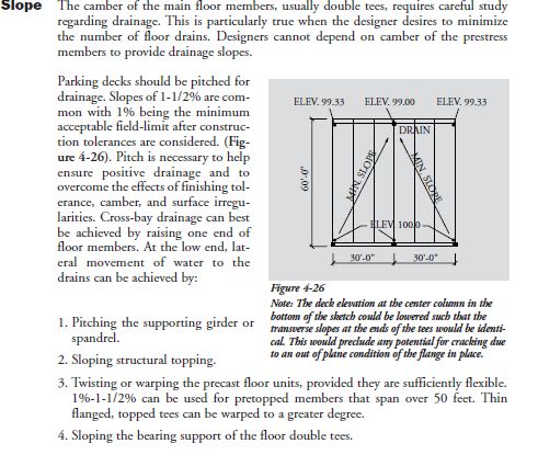
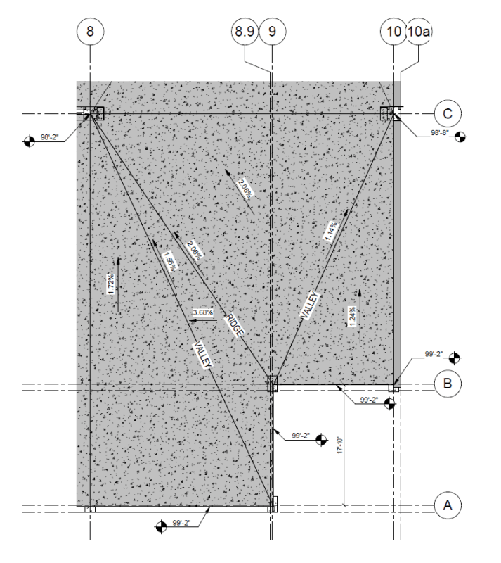
It is typical to get drainage in parking structures by having the bearing around the exterior of the structure level and then dropping one end of an interior beam to create a warped deck. This creates torsional twist in the member but given the slenderness of flange and each of the two stems, they do not have a great deal of tortional stiffness.

I have done a lot of structures with 1" across a 10' tee which puts the bearing 1/2" differential slope.

I am working with an architect that wants 2.75" on a 10' tee which is considerably farther than I have done in past projects. Does anyone have experience or rules of thumb as to how far you can twist a prestressed double tee before you start running into problems?

To be more specific, on a 24" x 10" DT x 47' long, would you be comfortable with both stems bearing at the same elevation on one end and one stem being 1.375" lower elevation at the other?
 
Replies continue below

Recommended for you


I would be comfortable if both stems bearing at the same elevation on one end and one stem being 8" lower ( lowest pt ) and the other stem 5" ..

The following excerpt from PCI Parking Structures: Recommended Practice for Design and Construction..


Parking_str._roof_slope_jxzrxc.jpg
 
Thanks for the reply HTURKAK.
This is a 2-bay garage.
The architect is calling for a girder with a cross slope of 2.2% for the bearing at the center of the structure. The spandrels at the perimeter will all be level. The PCI recommendations are for 1% - 1.5% for pretopped tees. My structure has 2" flanges with 4" cip topping.
It says that on thin flange tees you can go more than 1.5% but does not give any indication as to how much more.
I am rather gun shy at the moment because on my last DT project, we had one tee that was found to have a 1.5-mil crack the full length of the flange just inboard of one of the stems after it was erected. I can only assume that this was caused by the tee getting warped at some point during erection.
 
 https://files.engineering.com/getfile.aspx?folder=bbb78153-a4e6-45bb-bac2-4ea96cecd59c&file=2T-203-3.jpeg
can you use some of the topping to create slope? Doesnt take much to direct water.
 
Right now, the architect is calling for 2.2% cross slope which is 12" over the 45' girder length. I would prefer to see the warping between 1% and 1.5% but that would mean about 6" extra topping which adds up to a lot of concrete and additional dead load (and seismic in high SDC D).

I am planning to see if we can drop the whole girder 6" and then the low side an additional 6" which will cut the warp to 1.1% but leave the garage with mostly the same geometry.
 
I have designed a lot of garages with 12ft wide x 60ft long pre-topped tees. It was typical to warp them 2" (corner to corner). We had good results with that amount of warping. On jobs where we pushed past that limit, you would see a few tees with torsional cracks at the ends.

We rarely produced field-topped tees, but it is my understanding that they are far more flexible and would tolerate a higher degree of warping. Not sure how much more. 2.75" across a 10ft tee that's only 47ft long does sound like a lot.

It was also common practice to have the floor level along the bearing ends at the exterior on most of the projects. Though, they all would slope down some along the non-load bearing ends. The high end of the girder would be 4" to 6" lower than the corners. Then the beam would slope down an additional 2" for every 12ft of length (8" for 48ft girders).
 
This is what I am proposing to the architect.
by dropping the high end of the girder from FF to -6" I cut the warp from 2.2% to 1.1% which feels a lot better.

slope_study_2_sv1ams.png
 
Yes. That will work a lot better.

You might also want to think about what's happening with surface alignment at that re-entrant corner. If you were to ignore camber, that point at B-10 would want to be about 2" lower so the tees left of line 9 are close to flush with those on the right side of line 9 at B-9.
 
Thanks @Jarm013.
I have been having an internal debate with myself regarding the B/9 corner. In the original layout where the girder on C was at 99'-2" on the right and 98'-2" on the left, the difference in the slope of the 1st long tee to the left of 9/B was at -1¼" below the bearing at 99'-2". That actually worked out pretty darn well because the predicted camber at 17' was +1.29" so very little differential elevation at the junction.
As pointed out, the new scheme will put the left plane about 2" low so I may need to make an adjustment to the bearing on B / 9-10.
Of course, while my design software gives me 0.00" precision on camber predictions, in truth it is still just a SWAG and the accuracy of that prediction is not something that should be taken to the bank. It is often a fool's errand to chase it too hard.
 
Status
Not open for further replies.

Part and Inventory Search

Sponsor