Continue to Site

Eng-Tips is the largest engineering community on the Internet

Intelligent Work Forums for Engineering Professionals

  • Congratulations KootK on being selected by the Eng-Tips community for having the most helpful posts in the forums last week. Way to Go!

Weak-Axis Strength on Runway Girder (Design Guide 7)

Status
Not open for further replies.

Italo01

Structural
Sep 4, 2021
169
Hello guys,

I'm studying AISC's Design Guide 7(Industrial Buildings Design) and i have a question about a design example of the Guide. The question is about Weak-axis flexure in the example 14.1.1. I undersand that, since the transverse impact occurs on the top flange only this flange can be counted upon for strength and deflection. For the deflection calculation, the moment of inertia of the section is halved, which i consider correct, but the bending strength is not. The guide considers the full strength of the section.

Is the solution wrong or is there something that i'm getting wrong?

Thanks.
 
Replies continue below

Recommended for you

Italo01 said:
1) ...since the transverse impact occurs on the top flange only this flange can be counted upon for strength and deflection.

2) For the deflection calculation, the moment of inertia of the section is halved... but the bending strength is not.

1) This accounts for a transverse force, but it is not necessarily an impact. It's a 20% allowance for (transverse) operation of the trolley while carrying full load.

2) The bending calc is for "web sidesway buckling". The tension (bottom) flange can buckle when "the flanges are not restrained by bracing or stiffeners and are subject to concentrated loads" (from trolley operation). This calc is for the entire beam (y-axis bending), so it's appropriated to use the full y-axis section modulus for the calc.

 
Thanks for your response, SlideRuleEra.

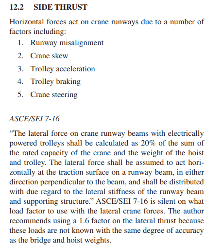
1)When the text says that "The lateral force shall be assumed to act horizontally at the traction surface", the traction surface isn't the compression flange for overhead cranes and tension flange for underhung cranes?

TextRunway_Girder_xmbrlw.png


2) What i'm talking about is equation 14-1a, so its not considering web sidesway buckling.
 
I didn't understand bigester93. The Girder will be with the strong axis vertical where the greater forces will be applied but, accordingly with code, the girder will also be subjected to horizontal forces, so i don't see how i'm able to avoid weak axis bending.
 
Italo01 said:
When the text says that "The lateral force shall be assumed to act horizontally at the traction surface", the traction surface isn't the compression flange for overhead cranes and tension flange for underhung cranes?

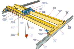
Design Guide 7 concerns CMAA "Specification for Top Running Bridge and Gantry Type Multiple Girder Electric Overhead Traveling Cranes", (see introduction to Chapter 10).
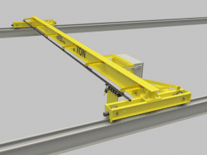
I suppose this would include the following arrangements:

Crane-1_nhy5z4.png

Crane-2_ikmtdv.png


but, in both cases the (traction) runway flange is the compression flange... and your question is about design of the runway (Chapter 14).

Reread Design Guide 7, starting with Chapter 10 "Industrial Buildings With Cranes", and keep in mind the CMAA specification about "top running".

Concerning equation 14-1a... review the first two sentences of of section 14.1:

...crane runway beams are subjected to both vertical and horizontal forces from the supported crane system. Consequently, crane runway beams must be designed for combined bending about both the x and y axis.

Equations 14-1a and 14-1b are the mathematics of combining simultaneous two-axis bending. The principle behind these equations has been accepted for a long time, there is nothing special about using them for crane runway beam design. Similar equations have been used for "general purpose" beams made of steel, wood, etc.
 
I didn't understand bigester93.

Not much posted by this member makes any sense; even less is relevant. At best bigester93 is a software salesperson, or possibly even a bot.
 
Italo01 - Be warned, the above post was almost certainly generated by a member using ChatGPT. (Read other posts this member has made, in some the member clearly stated that AI was used). This response omits a key technical issue, and there is another clue.

 
Note: The post that I stated was prepared by ChatGPT is NOT by bigester93. The one I was referring to has apparently been deleted without leaving a trace by Engineering Tips management... Good Move!

 
Thanks for the responses.

I´m sorry for not answering soon but i was too busy theses days and didn´t log in the forum.

SlideRuleEra, i´ll study carefully the design guide. Thanks for the help.

I hope that this forum doesn´t end up infested with nonsensical responses generated by AI.
 
Italo,

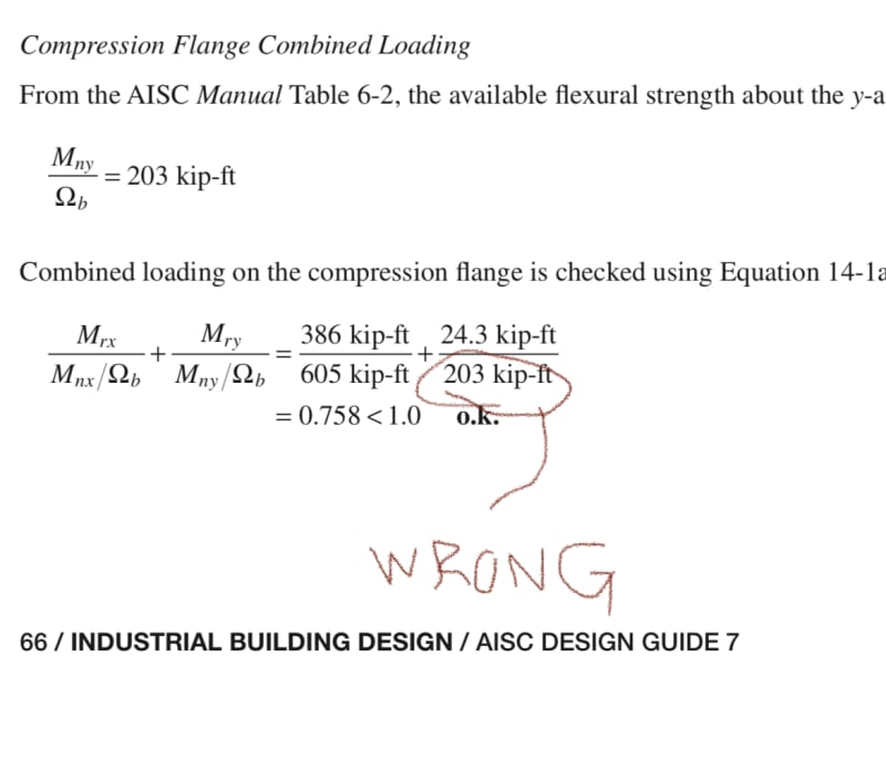
I agree with you the strength interaction in the design guide has a mistake (for W24X31).
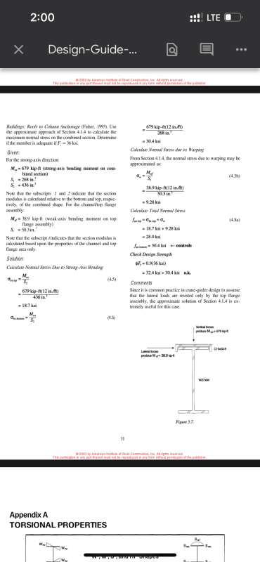
In the example you mentioned they used the full weak axis bending strength when they should have used half (top flange only). If you look further in the document where they calculate the strength of a W+cap channel, they use only the top flange assembly to encapsulate the lateral strength, which I believe was there intention in the first example you mentioned. If you look towards the end of AISC design guide 9, you will find another crane girder design example, which uses similar design principles, although slightly outdated. I believe you can also find examples from Civil Bay (I think on either AISC Steeltools or Civil Bay website).
7248125C-3262-4874-B989-C9902612CAC8_vcmipw.jpg
47ED26BA-B3ED-4AFF-AFD5-031D44236939_a4vd0d.png
 
Status
Not open for further replies.

Part and Inventory Search

Sponsor