I am analyzing weld stresses during vibration for fatigue. The mesh consists of shell elements.
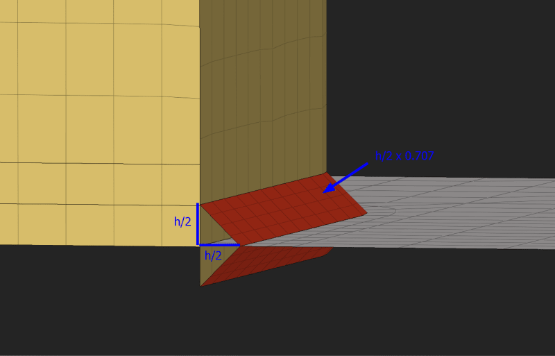
When modeling fillet welds, I set the weld size to half the actual weld size, to simulate a mid-surface. I set the weld elements thickness to the effective throat size:

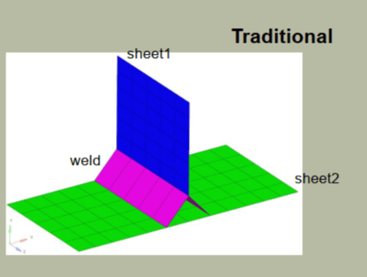
The weld is modeled using multiple elements, instead of a single element, which I sometimes see being done:

The nodes of the parent component elements are not equivalenced, so the load is carried only via the weld.
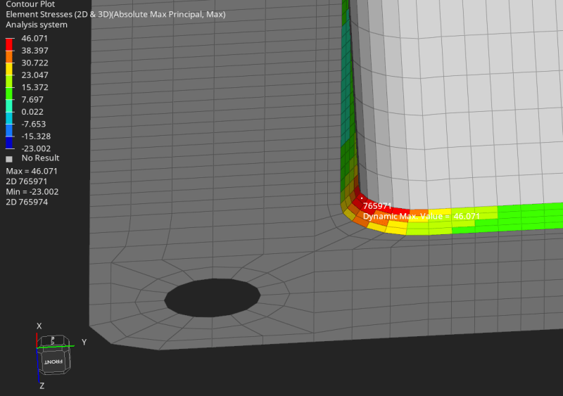
The results show a relatively large tensile stress (for fatigue life) in the weld elements. I'll get lower values if I mesh the weld using a single element for the weld, so I'm not comfortable meshing the weld with only 1 element:

My questions are:
1. Is this the correct method for modeling the welds?
2. Should I be considering the stress values in the weld itself? Or ignoring those and considering the results in the parent materials at the weld interface?
When modeling fillet welds, I set the weld size to half the actual weld size, to simulate a mid-surface. I set the weld elements thickness to the effective throat size:

The weld is modeled using multiple elements, instead of a single element, which I sometimes see being done:

The nodes of the parent component elements are not equivalenced, so the load is carried only via the weld.
The results show a relatively large tensile stress (for fatigue life) in the weld elements. I'll get lower values if I mesh the weld using a single element for the weld, so I'm not comfortable meshing the weld with only 1 element:

My questions are:
1. Is this the correct method for modeling the welds?
2. Should I be considering the stress values in the weld itself? Or ignoring those and considering the results in the parent materials at the weld interface?
