Continue to Site

Eng-Tips is the largest engineering community on the Internet

Intelligent Work Forums for Engineering Professionals

  • Congratulations KootK on being selected by the Eng-Tips community for having the most helpful posts in the forums last week. Way to Go!

Weld Modeling 1

Status
Not open for further replies.

Gowrath

Mechanical
Jan 8, 2010
17
I am analyzing weld stresses during vibration for fatigue. The mesh consists of shell elements.
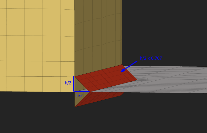
When modeling fillet welds, I set the weld size to half the actual weld size, to simulate a mid-surface. I set the weld elements thickness to the effective throat size:
section_tirwb1.png

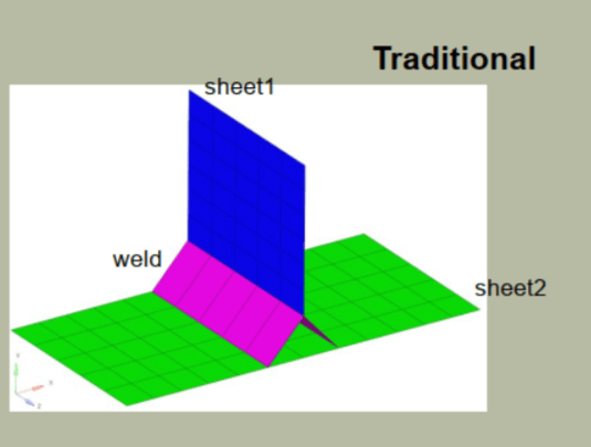
The weld is modeled using multiple elements, instead of a single element, which I sometimes see being done:
altair_weld_rahgbk.png

The nodes of the parent component elements are not equivalenced, so the load is carried only via the weld.

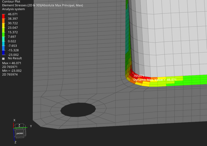
The results show a relatively large tensile stress (for fatigue life) in the weld elements. I'll get lower values if I mesh the weld using a single element for the weld, so I'm not comfortable meshing the weld with only 1 element:
results_dxffyy.png


My questions are:
1. Is this the correct method for modeling the welds?
2. Should I be considering the stress values in the weld itself? Or ignoring those and considering the results in the parent materials at the weld interface?
 
Replies continue below

Recommended for you

Check the article "Modeling Welds for Finite Element Analysis (FEA)" on the Apollo Engineering blog. It compares different approaches to weld modeling and their accuracy. The choice of the simplification level and the location of stress probing also depend on the method used for fatigue evaluation. I would try different ways of representing the weld and compare the results. Possibly using a simple test model.
 
TLDR (the Apollo blog) though I'm sure it's immensely valuable.

I don't get why people want to FEA welds.

What do you use for material properties ? of the weld material, for the heat affected zone ?

"Hoffen wir mal, dass alles gut geht !"
General Paulus, Nov 1942, outside Stalingrad after the launch of Operation Uranus.
 
Fatigue evaluation of welds using FEA is really common in various industries. There's even a separate module in one of the main fatigue analysis programs meant for such studies and it uses the structural stress method which is mesh-insensitive in theory.
 
"I don't get why people want to FEA welds."
I want to analyze a structure that undergoes cyclic loading. The welds, or the areas adjacent to the welds, are going to fail well before the parent components. The welded joints and loads are not straightforward. How do you recommend that I analyze the welds?

"What do you use for material properties ? of the weld material, for the heat affected zone ?"
Those properties are not relevant to the interpretation of the allowable stress ranges, as they are integrated into the standard (In my case, BS7608). For a particular joint, I consult the standard for the allowable stresses for the joint type and class. What I'm concerned with at the moment, is extracting the most accurate stress results. Whether the HAZ is more brittle or the weld is stiffer/stronger are separate issues.
 
"Fatigue evaluation of welds using FEA is really common in various industries. There's even a separate module in one of the main fatigue analysis programs meant for such studies and it uses the structural stress method which is mesh-insensitive in theory."
I'm having a hard time understanding how it can be mesh-insensitive, especially since that's not what I'm seeing when I test various weld meshes, unless I should ignore the results in the weld itself and focus only on the results in the parent materials.
 
Ok, what material properties (eg E) are you using for weld material and HAZ (I assume it's different) in order for the FEM to tell you stress ?

have people validated thee FEAs with real data (like strain gauges) ?

How good is the s/N curve ??

I would rather believe a load based assessment ... test a weld with specific loads applied (like loads applied to the welded structure and not to the detail weld).
Then you'd understand the allowable in terms of load, and for adopt less detail orientated FEMs to determine the strength of your structure.

"Hoffen wir mal, dass alles gut geht !"
General Paulus, Nov 1942, outside Stalingrad after the launch of Operation Uranus.
 
I found this white paper by Weaver Engineering especially useful when considering weld FEA as it connects hand calculations with FEA results that is mesh independent (sans singularities). There is sufficient details in it for the results to be replicated using FEA software of your choice. A good writeup behind the calculation methods can be found by Blodgett and others. One I found online is here.

Good luck!
 
I work with shell models almost exclusively for pressure vessels, but for our weld fatigue analyses we use 2D or 3D solid models where you can model the fillet. I wouldn't trust stress results of shell model welds because of the sharp edges/singularities. As you saw, their stress values are very mesh dependent.
 
Status
Not open for further replies.

Part and Inventory Search

Sponsor