Continue to Site

Eng-Tips is the largest engineering community on the Internet

Intelligent Work Forums for Engineering Professionals

  • Congratulations cowski on being selected by the Eng-Tips community for having the most helpful posts in the forums last week. Way to Go!

Welded rebar anchorage in thin wall

Status
Not open for further replies.

LockeBT

Structural
May 9, 2021
55
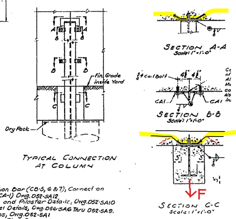
I'm reviewing some old drawings for a perimeter wall I'm going to retrofit. The structural system: free-standing concrete wall supported out-of-plane by cantilever steel columns embedded in piers.

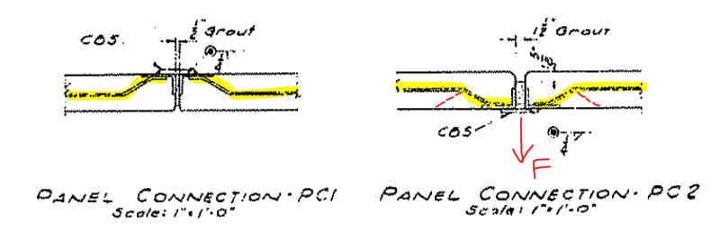
The wall panel to column connection is through embed plates with welded diagonal bars developed them into the wall. No anchor bolts. I have seen research done by Simpson StrongTie where these supplemental reinforcements are engaged and effectively enlarge the break-out failure cone. However they had anchor bolt in their testing. Curious to see if these were actually meant for anchorage.

InkedPanel_to_Panel_LI_oobul5.jpg

InkedInkedColumn_to_Panel_LI_sk9ooe.jpg


Replies continue below

Recommended for you

You might be over complicating this. You can check the connection for out of plane shear these using shear friction. The bar is developed with a development length on one end and then welded to the plate on the other end. Shear plane is through the thickness of the wall panel.
 
GC Hopi

That was my original thought. However in modern detailing there are typically anchor bolts in those embeds and it's always an anchorage check even with those diagonal bars present. With the amount of strength I get from shear friction and I can just preclude all the anchor bolts (and anchorage checks). But that seems like...cheating.

Also since the bar is bent shear friction only works in one direction. It won't work when the bar is in compression per ACI 318.
Shear_Friction_wzykgk.png
 
Understood. You are confident there are no studs. What is the condition of the panel connection? Are you increasing the out of plane loading? You can try a strut tie model or field test one of the panels. I think ACI has some test data and equation for concrete failure at rebar bends.

Screenshot_xabxrs.png
 
In the compression case you can still use the strength of the rebar in shear just not the shear friction equations. In your particular case you could use shear of the rebar or shear strength of the concrete.
 
The panel connections are in good condition as inspected. We're going through a voluntary process of seismic retrofitting our facilities. So while we're not adding any force to the panels (ie thickening it), evaluating the seismic forces based on today standards results in an increase in the force anyway.

I am curious about how you evaluate your anchorage capacity in that detail (with the force parallel to the anchor bolts). How do the DBAs come into play when it comes to break-out capacity?
 
OP said:
Curious to see if these were actually meant for anchorage.

Section B looks suitable for out of plane anchorage but, in my opinion, sections A & C do not. Those look to mike like connections meant for in plane shear transfer, possibly in plane tension connection, and maybe incidental out of plane maintenance of the joint for bowing etc.

GC_Hopi said:
You might be over complicating this. You can check the connection for out of plane shear these using shear friction.

I disagree. I'd only put stock in shear friction if the rebar were coming off of the angle leg running perpendicular to the wall panels. Otherwise there's way to much flex in the system to generate clamping on that interface.

OP said:
With the amount of strength I get from shear friction and I can just preclude all the anchor bolts (and anchorage checks). But that seems like...cheating.

You're right, it is cheating. Shear friction might get the forces across the joint and into the concrete on the other side but they do not solve any concrete breakout issues once you're on the other side.

GC_Hopi said:
In the compression case you can still use the strength of the rebar in shear just not the shear friction equations.

I disagree with that too. In the load direction that would put the rebar in compression, I think that it's just a version of a punching shear check.
 
KootK,

Just to pick your brain since you are here. I have seen modern versions of this type of detail used in tilt-up. Whenever they have a steel beam framed into a wall, besides the nelson studs on the embed plate, there are these welded diagonal rebars developed in both direction (usually 2 in each direction per bolt). The wall anchorage calc I did never took those bars into account. What do you think they are for?

If my description is not clear I can add an image. Let me know.
 
In my opinion, those mustache looking bars are primarily about dragging loads parallel to the embed plate into the surrounding concrete. For that, I believe that they are fairly effective. But, again, that cheating thing. In my opinion, having dragged the load into the concrete through the rebar does not mean that there isn't still a concrete pryout failure mode. I've done a fair bit of precast work and find the connection design in that space to be... somewhere between aggressive and optimistic. I'm all in when it's backed by testing of course.
 
Dr. Naito has done some research that might be of interest to you. It is for dry chord diaphragm connections, but there are some connections that will be of interest. Dr. Naito Study

The tilt world has a number of standard details they use that have been around for eons. The CSA handbook shows them too. Once you get into thin wall sections it is not easy to find info. We have sponsored a research student for the year to test a number of ours.
 
Status
Not open for further replies.

Part and Inventory Search

Sponsor