Continue to Site

Eng-Tips is the largest engineering community on the Internet

Intelligent Work Forums for Engineering Professionals

  • Congratulations KootK on being selected by the Eng-Tips community for having the most helpful posts in the forums last week. Way to Go!

Welding Aluminium - NX Nastran

Status
Not open for further replies.

nvhuser

Automotive
Nov 5, 2014
25

Hello everybody, I have some experience creating the FE models for the spot welds of steel structures like body-in-white (normally I use RBE3-CHEXA). Now, I am working for a new company where the body-in-white has some aluminium parts. Should it be expected a difference in the modelling of the spot welds? Is RBE3-CHEXA acceptable?
Thank you

 
Replies continue below

Recommended for you

Hello!,
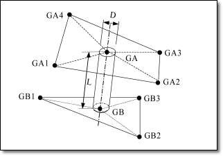
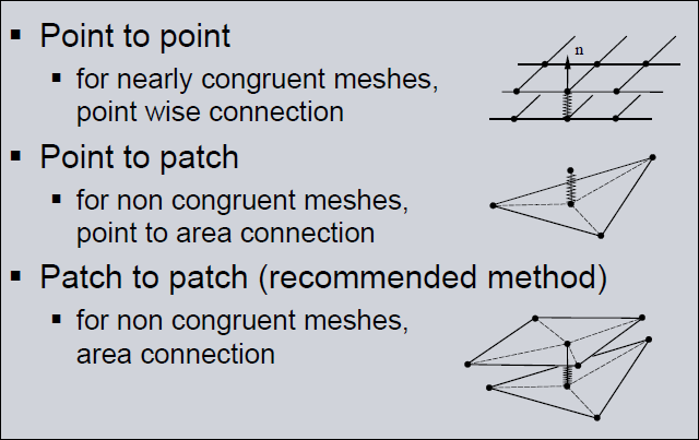
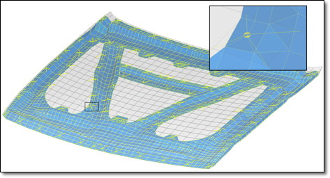
I will use in NX AdvSim with NX NASTRAN the CFAST/CWELD Connection command to create NX Nastran CWELD type connections in Advanced Simulation. In NX Nastran, you use CWELD elements to model connections, such as fasteners, spot welds, or rivets, between multiple sheet bodies.

cweld_format_c9ax6q.png
cweld_tipos_conectividades_ihxoje.png


CWELD point-to-point connections provide alternatives to traditional NX Nastran connection methods, such as CBAR, RBE2, or RBE3 elements or MPC constraints. In general, CWELD connections are easier to create and use. Although there are a number of different ways to model structural connections and fasteners in NX Nastran, such as with CBUSH or CBAR elements or RBE2s, CWELDS are generally easy to generate, less error-prone, and always satisfy the condition of rigid body invariance.

cweld_FEmodel_uicp1m.png


Take a look to this post in my blog where you have a video included:

Best regards,
Blas.


~~~~~~~~~~~~~~~~~~~~~~
Blas Molero Hidalgo
Ingeniero Industrial
Director

IBERISA
48004 BILBAO (SPAIN)
WEB: Blog de FEMAP & NX Nastran:
 
Hola Blasmolero!

Thank you very much for your reply, in fact CWELDs are very useful connectors - indeed, I use them quite often in some seat models. My perception is in the company that I am working for they want to avoid the usage of this kind of connectors, sometimes if they have the same numbering than other includes, which is tolerated by CWELD elements, the SOL200 (optimization) refuses to run until you solve these numbering conflicts.

The purpose of using CWELDs will be to perform an optimization task (FRF-Match of the test data), which parameters could be optimized (e.g., young modulus)?
I would check the quick reference guide in order to understand the difference between using CHEXA-RBE3 and CWELD connectors. Do CWELD elements have advantages in terms of the number of design variables?

Although the main question that I need to answer is related simultaneously to CAM and CAE -> what are the main differences between the welding process using aluminium and using steel structures? How could we simulate the effect of spotwelding between two aluminium parts using Nastran? Is it just changing the material property from steel to aluminium (changing the Young modulus from 210 to 70 GPa)?

Thank you very much for your assistance!
 
Status
Not open for further replies.

Part and Inventory Search

Sponsor