Continue to Site

Eng-Tips is the largest engineering community on the Internet

Intelligent Work Forums for Engineering Professionals

  • Congratulations SSS148 on being selected by the Eng-Tips community for having the most helpful posts in the forums last week. Way to Go!

Welding HSS to base plate - matching results to Risa

Status
Not open for further replies.

RabitPete

Structural
Nov 24, 2020
109
Hoping someone could double check my math here, I am doing everything by AISC books and can not match the results with RISA connections.
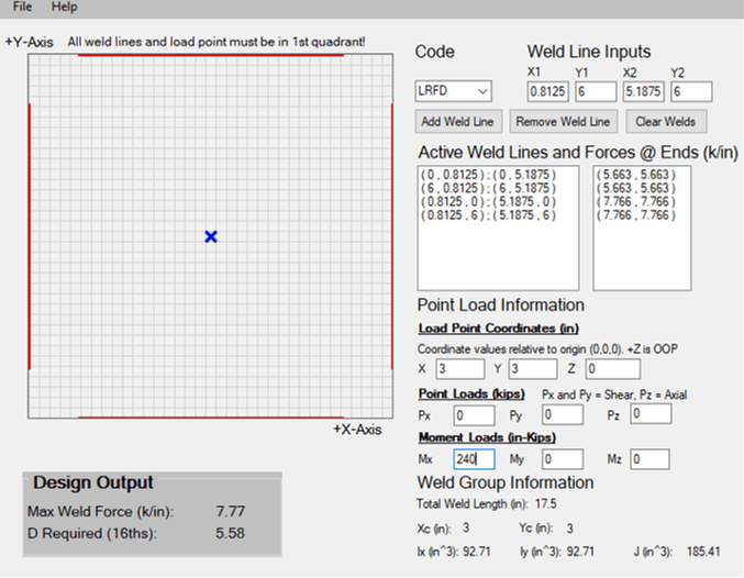
6x6x1/4 HSS subject to 240 kip-in load. 46ksi yield/58 ksi ultimate
5/16 weld (0.22 throat) Fexx=70

Since HSS wall thickness is 0.23 and 5/16 weld would not be develop Fexx, effective weld size Deff=4.31 and effective throat=0.191
Available weld strength ϕRn = 1.392*4.31 = 6 kip/in

Calculating moment of inertia: I=2(6^3*0.191/12+6*0.191*(6/2)^2) = 27.5 in4
And required weld strength for out of plane force per unit length: Ro=240/27.5*(6/2) * 0.191 = 5.0 kip/in

Now I am trying to calculate 2 connection in Risa connections. Available weld strength matches Risa results for different HSS, different weld sizes, so no questions here. Now required weld strength is a completely different animal. For the same conditions, Risa gives Ro=7.89 kips/in.

Moreover, my Ro does not change with the column thickness, while theirs does, e.g. 6x6x1/2 needs 9.66 kip/in while 6x6x1/8 only 7.23 kip/in
Are they accounting for ineffective length? I though it only applied to HSS-HSS welds. And if they do account for it, Ro would depend on base plate thickness and changing base plate does not seem to affect the results. Difference between 5 kip/in and 8 kip/in is substantial. What is the catch???


Replies continue below

Recommended for you

I don't know where to start, but suggest first to review the calculation of moment of inertia of weld. The formula below, represents Iw, and S. t is the throat.

image_zhdbwt.png
 
That is exactly what I used. And it looks like Risa is adding some sort of adjustment/ineffective length, which I don't see anywhere in the AISC for this type of connection.

I tried HSS to HSS connection as well, which does require calculating effective width. Ineffective length calculated from eq. K1-1 (A360-16) matched up with RISA for thinner base section, until a point where it started using a maximum effective length Be = to half of the HSS width (Bb/2), regardless of how thick the base member is, something AISC did not call for. K1.2a limits Be to <=100% of Bb, while RISA does 50%. It must be doing something similar with the HSS to base plate welds.
 
Are you sure the effective length limit is applicable to HSS welded to the plate? It seems to me that section K is applicable to HSS to HSS connection, and for plate weld to the web of HSS.
 
r13 said:
Are you sure the effective length limit is applicable to HSS welded to the plate? It seems to me that section K is applicable to HSS to HSS connection, and for plate weld to the web of HSS.
That is exactly what my understanding was, and we always designed thick plate/HSS welds without taking any ineffective lengths into consideration. So I am not sure why Risa is applying some sort of a correction. Unless I made a silly mistake somewhere. Need to get to the bottom of it, as 1.6 times is kind of a lot to be off by.
 
Does the program recognize you are attaching HSS to solid plate? You should contact RISA for explanation, if it is not already covered in the user's manual.
 
So after discussing with RISA, it appears that they calculate moment of inertia using 2 straight line segments (see below). Any resistance from corner welds, as well as other 2 sides of the column are dismissed. It appears to be over conservative, especially disregarding remaining sidewalls in case of a single axis bending moment. What do you guys think?
weld_gciysb.png
 
I would not worry about matching RISA. I would do my own calcs. When I get an HSS end plate connection with loads on every axis and bending in each direction, I typically apply a weld that develops the HSS wall.
In this case: 0.75*0.6*58*0.233/1.392 = 4.37 Sixteenths. So a 5/16ths fillet weld on the workable flats. Then ask EOR to verify HSS is satisfactory for the loads.

However, this assumes the EOR has done the due diligence to ensure the HSS is satisfactory for the loads.

If I do the analysis with the elastic method (only weld on HSS flats considered and 0.5" of weld discounted for starts and stops on each side), I find the maximum weld force is 7.77 kips/in and the required weld using LRFD is 5.58 sixteenths. This is greater than the maximum fillet weld to develop the HSS wall. Choose a thicker HSS and reevaluate. I find an HSS6x6x1/2 works with this method.

If this is not an option, you can add a note to the fabricator requiring them to weld beyond the HSS flat, then evaluate using more a more precise weld group w/ full welds on flats and corners.

Edit: For your specific example, the logic expressed by the RISA representative is correct. The load transfers from the bolts, to the plate, then to the welds. The vertical welds contribute much less than the horizontal welds and can be discounted.

Weld_Group_HSS6x6x1_4_vuvsnu.png
 
DrZoidberWoop said:
The vertical welds contribute much less than the horizontal welds and can be discounted
Using 4.375" long welds to match your data, discounting vertical welds increases required strength from 7.77 to 9.16 kips/in. Yes, they contribute less, but not insignificant. While adding the full weld with corners takes it down to 5.37 kips/in. 70% is quite a difference.

How do you guys come up with things like discounting 0.5" for starts and stops? What code is it in? Personally, I have never specified or seen HSS column which was not welded all around.
 
Interesting, base plate design in RISAConnection was done (I believe) after the mass exodus of technical folks when Netmsheck bought them out. I could be wrong, but I know I wasn't involved in it at all.

Some quick thoughts:
1) For any SHEAR loading, I would ignore the welds that are perpendicular to the shear force direction. So, that could make sense.
2) It is possible that they based their moment resistance for base plates on the End-Plate Moment connection for wide flanges. Where the assumption is that moment is resisted solely by the flanges of the wide flange. So, web welds don't contribute at all to this moment resistance. This (IMHO) would be perfectly acceptable for an I shaped column to base plate connection.
3) Then, it is also possible that they then used this same routine as the basis for adding HSS column to base plate connections. That certainly would be the quickest, easiest way to get this new feature into the program.

Note: My impression is that the collective engineering skill / knowledge has really gone down hill. So, I would more closely scrutinize any new features added since 2017/2018. If you disagree with this method and have an AISC example or Design Guide that you can point to that will demonstrate your point, then you should send it in to technical support and ask them to change it. Even if the new management / CEO is more concerned with Sales/Marketing than she is with engineering accuracy (which is my opinion of her) they still seem to be pretty responsive to user requests like this.... at least as far as I understand.

Caveat: I used to work for RISA and have some hard feelings with the current management over how my departure was handled. Plus, I now work for one of their major competitors. Therefore, I definitely have bias towards the current incarnation of RISA/Nemetshek.
 
I don't think the vertical welds contribute much to the connection shown. The prying action from the bolts isn't going to distribute the force to the vertical welds of the HSS very much. The vast majority will go to the horizontal welds.

I sometimes apply the 0.5" weld length reduction to account for workmanship and variance in HSS workable flat. It's conservative engineering judgement based on observing HSS coming out of the fab shop out back, so not code required. I don't do it for much else. I only assign all-around welds on HSS if calcs or EORs requires them, or if they're round, obviously. Different practices, nothing wrong with that.


Put everything said aside, I suggest always do your own calculation, and use the complete loop for weld performed in the shop, and take some discount for field weld.
 
I think we just found another discrepancy in RISAconnections. They calculate available tensile for anchors using 0.75Fu per AISC table J3.2 which is to be used for steel frames, not anchor rods. They also use a full area instead of effective cross section, ignoring reduction due-to threaded portion. Please correct me if I missed something but should not the Nsa for anchors be calculated per ACI 17.4.1.2 (Nsa = Ase,N*Futa) instead?

Interesting, how using a lower tensile strength and larger area results in nearly the same end result.


Thanks, makes sense. Simplified method gives more conservative results. Our anchor spreadsheet is based on ACI not AISC, so results are different. But how about meeting ACI ductility requirements? One still needs to calculate Nsa per ACI 17.4.1.2 and then multiply by 1.2.
 
RabitPete - did you consider the shear load in your weld calculation? I don't see it mentioned or included in the calculation. Unless the moment at the base is resisting only an eccentric axial load with lateral resistance above the foundation somewhere, your column will take a shear force as well. It is expedient and usually conservative to assume the sides of the HSS parallel to the shear force resist the shear while the welds on the faces perpendicular to it (and, therefore, with the greatest I) resist the moment. As long as one can take one and the other can take the other, you'll have enough all working together to resist everything.
 
For simplicity and to limit number of variables I used pure moment in both calculations. Risa does add shear later to the required weld strength as sqrt(Ru2+R02). They did simplify things, assuming only sides with the greatest I resist moment, so when moment is applied in both directions, each "set of sides" resists its own moment independently. Unfortunately this approach results in overly conservative solution for the single moment case.

Just trying to validate all the spreadsheets I inherited and make sure all the tools are in agreement with each other and to understand what code provisions they are based on, what assumptions were made and what are the limits of applicability.
 
Status
Not open for further replies.

Part and Inventory Search

Sponsor