Continue to Site

Eng-Tips is the largest engineering community on the Internet

Intelligent Work Forums for Engineering Professionals

  • Congratulations KootK on being selected by the Eng-Tips community for having the most helpful posts in the forums last week. Way to Go!

Welding thick T-joints 2

Status
Not open for further replies.

FRACH23

Structural
Aug 21, 2015
28
I am asked to support my team in Poland to assemble our own spreader/ lifting beam so we can transfer max of 84-ton tank/horizontal vessel. My exposure was more on industrial/ petrochem facilities but haven't used to welding thick plates.

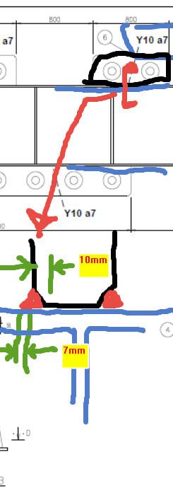
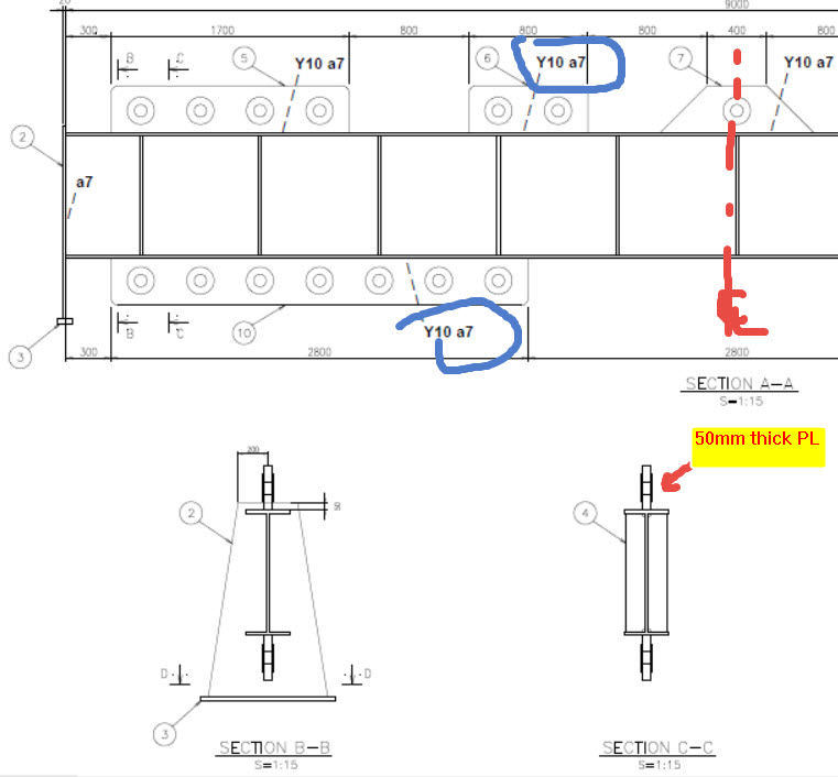
I generally proposed CJP to connect the 50mm top and bottom lifting plates to the hot rolled beam. I practice American Code and I am familiar only with U, J or V. Im not sure what the local fabrication group proposed to us instead "Y10 a7" weld (see attached dwg). Maybe its a 10mm partial penetration groove weld with 7mm extra fillet?
Y10_Weld_d4hxju.jpg
 
Replies continue below

Recommended for you

That should probably be a half V (10 mm deep) instead of a Y 10, but your conclusion is correct.

Make sure the calcs add up. You're using a 50 mm thick plate, but the weld is only equivalent to 34 mm approx.
 
thanks kingnero. A full penetration weld should have saved me calcs preparation. While the flange base weld is only 17mm x2, if I imagine correctly, the the addition of 7mm fillet would not do any extra for the eye pad plate.

The weld contact on the partial groove would just be 10*sqrt(2) x 2 since each side, a total of only around 28.3mm. Would that be a more critical limit state? By the wall sir, amm materials (plates, beams) were S355.


Y10_Weld_ztslic.jpg
 
The 7 mm value is throat, not leg. And yes, it would be helpful for the load transfer.
Don't do the 10 mm times sqrt(2), that would be overestimating the cross section. You effectively have 2x(10+7) mm times the weld length.

But the overall geometey is awkward. You want a 50 mm pad eye on top of a much thinner web. The wider you go on the flanges, the lesser the strength of the flange. Gussets would be helpful here, or a much thinner pad eye with thick shims to take up the slack of the D-shackles, if applicable.
 
I appreciate your effort to explain. Thanks a lot, kingnero. The spreader beam is to be carrying a max of 100 tons WLL resulting in a thick pad eye. Yes, we provided stiffeners for a good load path.

Your idea about a thinner pad eye was noted. We will just increase the round washer to thicken critical zones.

By the way...do you have any idea about the load test policy for spreader beams in Eurocode? Is it 125%WLL? I assume shackles, pad eye, and slings even need to have higher capacities like 2x WLL?
 
I always worry about PJP - not from a design perspective but from an application perspective.
10 mm depth of preparation will not necessarily get you 10 mm depth of penetration. (which the calculations are based on)
Depth of penetration is directly related to welding process used, size of electrode used, position of welding etc.
Much better to nominate Y15 or Y20 if 10 mm is minimum required.
Better to be safe than sorry - more is better than less when it comes to lifting applications.
 
Thanks Dekdee on this advice. B etter safe than sorry
 
See EN 13155 (and EN 13001-3-1) for non-fixed load lifting equipment (like spreader beams).
The previous version was rather simple (although still more severe than your proposition, at 200% WLL), the newer version demands a lot more calcs before you even get to the testing stage.

Can't help you for shackles and such, as they're commercially available and should be rated for the weight you're trying to lift.
Be warned that for Euro service, requirements for welders and procedure also follow out of the aformentioned standards.
This will also help with the 1/2 V 10 (or more) discussion, as cross sections (macrographs) will be required.
 
I suggest t= 25 mm with full penetration weld. Inspection with ultrasonic.

Regards
 
Status
Not open for further replies.

Part and Inventory Search

Sponsor