Continue to Site

Eng-Tips is the largest engineering community on the Internet

Intelligent Work Forums for Engineering Professionals

  • Congratulations KootK on being selected by the Eng-Tips community for having the most helpful posts in the forums last week. Way to Go!

Welding Wide Flange Splices 4

Status
Not open for further replies.

sedonas

Structural
Oct 16, 2015
82

When you weld two wide flange together by cutting them square... would it make sense to further strengthen the web by putting cover plates over the web? Or over the flange?The purpose of flange is for tension and compression.. the web is supposed to be only for shear? Which to focus more in welding.. But if you weld cover plates on the flange.. won't it weaken the flange by having many welded regions.. how do you weld your splices (that involves no bolted connection)?
 
Replies continue below

Recommended for you

First, it is rarely necessary to provide cover plates over a butt splice weld if the weld is done properly.

Next, the ends are initially cut square, but then are prepared to receive a complete joint penetration weld by a welder who is qualified to make such welds. In the US, the joint configuration can be either pre-qualified (meaning that it fits one of the many standard joint configurations) or it can be separately qualified by testing. Assuming the joint configuration is pre-qualified, then the next necessity is to have a Welding Procedure Specification that lays out the sequencing, size and type of weld to be used in that joint. Then the welder has to be qualified to the Welding Procedure Specification in the proper position of welding (flat, horizontal, vertical upward or downward, and overhead), using a particular welding process (gas metal arc welding (GMAW), flux core arc welding (FCAW), gas tungsten arc welding (GTAW) or the more common shielded metal arc welding (SMAW)), with a particular filler material (electrode) with the weld properties and position compatibility that you need.

All of these are laid out in the American Welding Society's codes and standards, the most common of which is AWS D1.1, Structural Welding Code- Steel. There are other welding requirements depending on the country you are in.

The purpose of the complete joint penetration weld it to achieve a splice that develops the full tensile strength of the member being spliced.

The completed weld should then be inspected and tested for compliance with appropriate standards using acceptable nondestructive testing methods such as ultrasonic flaw detection, radiography, or others as appropriate to the application. Rejected welds must be removed and the process repeated.
 
In most steel design, we don't consider heat affected zones affecting strength like in aluminum.

Very well said, Ron!

 
Pictures worth a thousand words:

This is a wide flange that is cut square and spliced.. we put cover plates on the web. But I told the contractor the main strength region of a wide flange is in the top flange and bottom flange..

Images showing the top and bottom portion of the wide flanged spliced welding at the web:
Jpq2xE.jpg


3VDXNi.jpg


This is at the back of it. Is it considered full weld?

BbRCcK.jpg


Whatever. I told them the flanges are the real meat of a wide flange where tension and compression can occur and told them to put metal plates on them too. What you make of this advice? Putting cover plates on the flanges would indeed make it sronger, wouldn't it.
 
First, you need to find a welder. Whoever made those snots on the beam can hardly be called a welder.

Best regards - Al
 
Agree with GTAW....those are some lousy welds. Also, from what you have shown, they are fillet welds on a cover plate that was maybe used as backing for a complete penetration weld. In any case...get a qualified welder.
 
Can you show pictures of the difference between fillet welds and complete penetration weld? In my place. ALL Welders are just ordinary workers who weld... maybe former masons or carpenters who need to make a living. They are not trained in any welding school, and there is none here. This is why some architects avoid steel structure because they are afraid of welding quality.

Btw.. the last picture shown above (reproduced below) are not fillet welds on cover plate.. they are supposed to be full penetration weld on the main beam as shown. Are they not? But they look bad (or missed it) so I told the contractor to go back and do more full weld as well as put cover plate on it.

BbRCcK.jpg


Again, are these not deep penetrating weld? What are these supposed to look like? Thank you.
 
The weld you show above is a very poor attempt at welding a complete penetration butt weld. There appears to be no joint preparation, no space between the two piece to be joined and poor technique in the welding. With this type of poor joint preparation, even a good weld would not penetrate the thickness of the web.

The fillet weld you asked about is on the cover plate on the opposite side. The welds are equally poor there.

The welding you've shown for this splice is dangerous.
 

So it's better to have wide flange splices connected with bolts and cover plates? I'd have the designer designed them instead of relying on welding.. so it's ok to have additional cover plates with bolts added to any existing welding (pretending the welding is not there)?

The welding methods were done to over 90% of steel structure in my country. We don't have school for welding.

The welding rod used is 6011.. what is your thought of 6011?
 
edit.. I plan to have the following (image is just sample from web) added and designed.. but why is there only 3 bolts in the web on one side? Why aren't there bolts in the other side of the web?

MAbVWR.jpg
 
Because the connection is shown with the web plate welded one side, bolted the other. This is often done with the flange plates as well. Considering the quality of the welds you showed, perhaps you should use bolts both sides on all the splice plates.
 
Yes. We will.. Is it easy to drill thru 10mm of flange thickeness (in the field)? How hard or easy is it? Can a normal drill machine be used or a huge one? What are others experience on this?
 
BbRCcK.jpg


According to the welder who did the above weld, it's not the direct weld but the other side of the full penetration weld.. the web is 0.250 inches (6.5mm), so when he did the full weld on the other side, it affects the side shown above. Why, what is supposed to be the appearance when your weld penetrates to the other side?
 
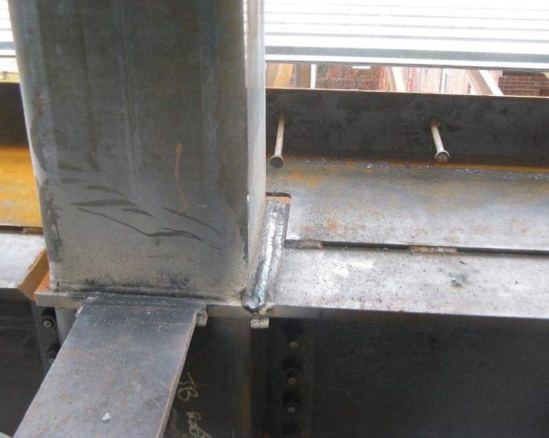
Just took a couple photo's recently, this is what a full penetration weld should look like. You can also see a proper joint preparation in the first photo.

SMC_SC_HSS_Moment_Weld_Fourth_Floor_fza8me.jpg


Typical_Finished_Bottom_Flange_ilkjsh.jpg
 
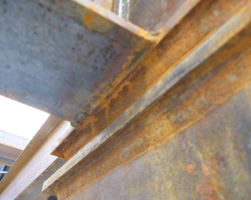
The welder did a back job. Here's in its completely (why is the portion in white?):

QLnRHl.jpg


Again, this is the back of the front full weld.. so apparently the weld has fully penetrated into the other side. I need more clear pictures of what the other side should look like. Maybe proper joint preparation makes the other side nice and smooth too?
 
If it were my job, I would politely tell the contractor that the welder should not work on the project again. Even his repair looks bad.
 
What kind of welding rods do you use for deep weld? We use the so called 6011.. here's what it says:

"The 6013 electrode is often used in situations that involve irregular or short welds that require a change in position because it provides a very stable arc and a smooth finish. The 6011 electrode is often the better choice on painted, dirty or greasy surfaces when appearance is not as important and more penetration is needed.

Read more :
 
Status
Not open for further replies.

Part and Inventory Search

Sponsor