Continue to Site

Eng-Tips is the largest engineering community on the Internet

Intelligent Work Forums for Engineering Professionals

  • Congratulations KootK on being selected by the Eng-Tips community for having the most helpful posts in the forums last week. Way to Go!

What are the limits of prescriptive design? 9

DTS419

Structural
Jun 21, 2006
162
The IRC, as we are all familiar, provides prescriptive design standards meant to cover common construction of “one and two family dwellings and townhouses up to three stories.” Examples of this prescriptive design include connections such as from wall to foundation, headers over openings, etc.

But what are the limits of these prescriptive provisions, and whose responsibility is it to identify them?

Let’s take a closer look at connections to foundations, for example. It’s not uncommon for large custom homes that fall within the IRC’s scope to have finished basements with tall ceilings resulting in deep foundation walls with significant unbalanced soil load. There can also be significant uplift loads that must also be transmitted to ground depending on the proportions of the superstructure. These forces can easily exceed the capacities of the prescriptive provisions, that, if I had to guess, were developed long ago with simpler construction in mind.

It’s also not uncommon for many home builders to skip architects and engineers and simply follow the IRC. I’ve seen too many projects where this happens, and the result is connections that are over capacity, lateral systems without adequate diaphragm and shear wall detailing, etc. This often doesn’t result in total failure, but rather a final product that doesn’t meet current standards of practice, making it hard to call the builder’s attention to flaws with “the way we’ve always done it” that might be code compliant but not necessarily sufficient. And of course, failures can and do happen in the worst cases.

So what mechanisms, if any, are in place to ensure that simply following prescriptive codes are adequate for every situation, and whose job is it to identify when an engineered design is required? And, who is responsible if a code compliant prescriptive design ultimately proves to be inadequate for the situation?
 
Replies continue below

Recommended for you

I suppose the prescriptive part of the IBC makes some sense to be calibrated to the IRC given they are employed in fairly similar fashion and scope, but I'd hesitate if the IRC is going to be based on an "engineered" lower safety because hypothetically a high occupancy restaurant or maybe a modest church could happen as prescriptive IBC. I've vary rarely seen any IBC prescriptive design.

If the IRC got a but of a structural brush up, I think that would be fine, particularly if some of these prescriptive "designs" were run through calculations and the (presumed] differences in the safety factors could be brought into closer alignment or selected in a deliberate sense. I could see a floor joist being "less safe" versus say a wall stud that could produce a larger failure like collapse versus a dip in the floor screwing up your game of marbles. Different failures could have different levels of safety slash reliability. Bending overstress versus deflection, for example. Wood crushing versus compression buckling in a wall stud.

In terms of moving the bar, just publishing engineered components based on the various design conditions would be a start, let the various zealot (non derrogatory) groups carry the ICC revision spears. Maybe six articles in structure magazine would get a strong atart.

Start with the basics, floor joists don't have a lot of variables in the code, it's floor dead load and live load, minimal seismic effects and typically no snow. You wouldn't have to go too far into this, as relatively few species are popular. Floor joists themselves aren't that popular. And on the topic, what are the presumptions for "replacement" prescriptive designs like I-Joists, you could follow start. Compare the engineered versus the IRC for one species or two to keep the tables digestible.
 
great points lex on adjusting safety factors for the specific limit state and differentiating between life-safety and performance. funny how we use the same handrail safety factors whether it protects against a drop of 1 ft or 1000 ft.

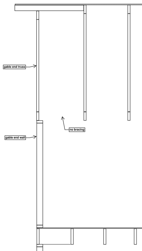
RWW, you mentioned the gable wall hinge and it got me to digging again. IRC does not appear to prevent me from building my gable end wall with a hinge as sketched below.
Screenshot_2024-06-16_072603_zyni40.png

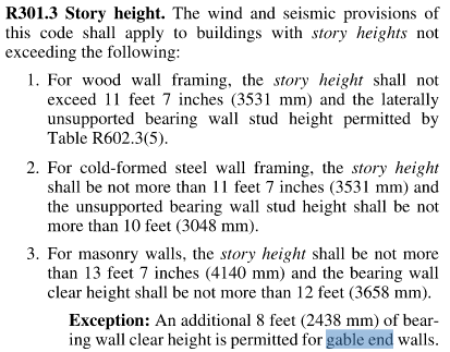
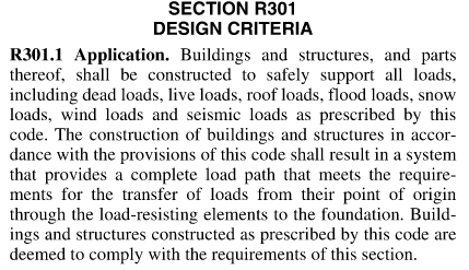
I know the truss is an engineered element, but typically in the commercial realm it's the engineer of record's responsibility to call out bracing since the engineer of record typically owns the wood wall and global stability design. I would not be surprised if residential roof truss suppliers do not design their truss bracing to support my wall. should IRC at the very least have a detail for this common scenario? the wood portion of the IRC appears silent, but the passage below indicates that perhaps the committee's intent is for walls to be framed full height without a joint.
Screenshot_2024-06-16_073747_o9vvlx.png

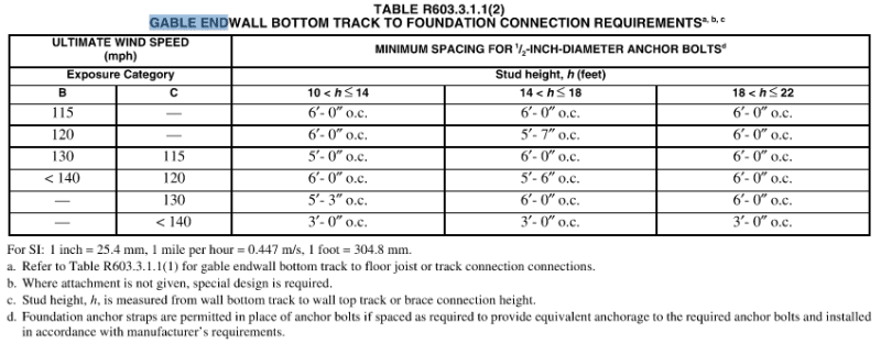
within the cold form portion, the following table appears to support this hypothesis, it varies bottom track fastening based on stud height. to tell you the truth tho I don't do much cold form, and the table does not make sense to me. seems like you would want to call out max spacing, not min spacing. also the spacing values listed in the table seem to have experienced some kind of a printing error. I'm not an expert in this tho, somebody let me know what I'm doing wrong here.
Screenshot_2024-06-16_073444_ynkjy6.png

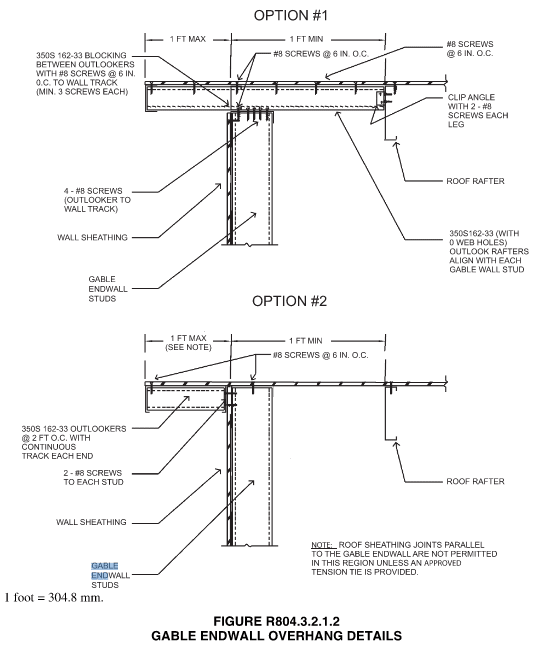
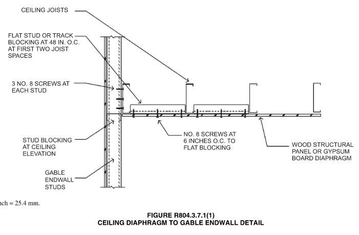
the following is the only sketch of the gable end I could find. it also supports the hypothesis that the committee's intent is to ban the truss to wall hinge, since the sketch shows a wall.
Screenshot_2024-06-16_073208_og5wws.png

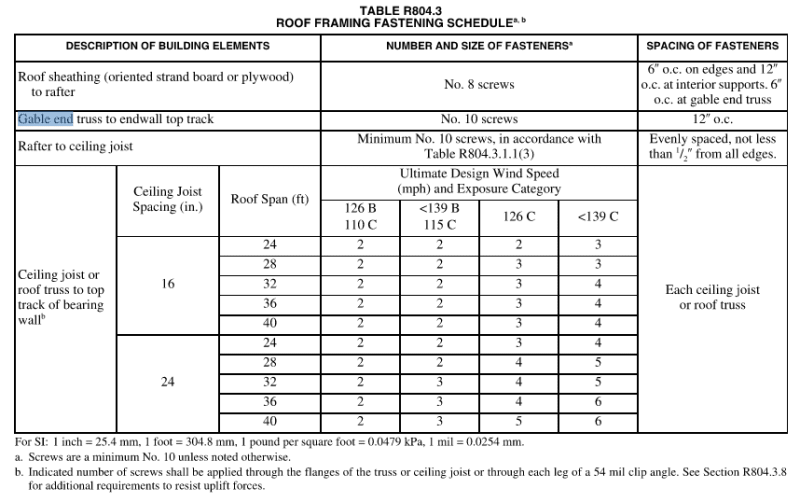
however, that hypotheses is largely shut down by the table below, which specifically calls out the required fasteners between gable end wall and gable end truss.
Screenshot_2024-06-16_073308_fmdtis.png
 
Mike Mike said:
RWW, you mentioned the gable wall hinge and it got me to digging again. IRC does not appear to prevent me from building my gable end wall with a hinge as sketched below.
The detail does not show a sheetrock nailer or sheetrock which is what typically braces it - for better or worse. in high wind areas, the IRC requires balloon framing (at least in the NC version)
 
Rail isn't required below like a 30" drop, but you'd want to meet the code if you put it there from a design engineer standpoint, so, point conceded.

Irc requires a continuous load path so that's where it's outside the code for the hinged gable end. You'd rather stick frame it up to the roof on the end. Alternately you are relying on diaphragm action of the gypsum board ceiling and that's how they sometimes survive, though they usually manifest damage when the wind load is high enough.

I so dislike light gage being in the IRC. That belongs in a separate industry published standard. Let's be real.
 
lexpatrie said:
Alternately you are relying on diaphragm action of the gypsum board ceiling and that's how they sometimes survive,
Well it is likely that over 90% of the houses in the US rely on the gyp ceiling diaphragm. It seems to perform remarkably well considering. Back when Fran came thru our area, I did not see any failures of gyp braced gable ends. Saw one poorly framed gable end pushed in where a vaulted ceiling existed though.
 
XR250 said:
Well it is likely that over 90% of the houses in the US rely on the gyp ceiling diaphragm. It seems to perform remarkably well considering. Back when Fran came thru our area, I did not see any failures of gyp braced gable ends. Saw one poorly framed gable end pushed in where a vaulted ceiling existed though.

That pretty much sums up most of the issues with IRC. There is a lot of what I call voodoo, that is materials and components functioning in a way no one would ever design for, that helps explain why most builders get away with “this is how we’ve always done it”.
 
@ Mike - Gable wall hinges come in several forms - and gable trusses are definitely one of them. We also see gable walls framed up to ceiling level and then a new stud ceiling to truss alot. Truss packages often come with a detail for bracing gable trusses out of plane, but my understanding is that this takes care of the wind on the face of the truss but does not take into account the wind from the wall below. Even at that it is better than nothing. Like many I prefer baloon framed gable walls or an adequately braced "hinge"

I agree that the gyp ceilings have historically carried this load and appear to perform ok in general, especially for that single story ranch I mention above. Where I feel like we may start to see issues are when these same provisions are applied to ever-more-complicated designs with high ceilings, lack or adequate braced wall at perimeters, open floor plans with fewer interior gyp walls, etc.

We recently had some tornadoes around here and there definitely appeared to be alot of gable wall failures. I was not involved in many investigations as it was mostly residential damage, and did not want to be a gawker, so most of my observations was just from quick glances from the road. Lots of apartment buildings with gable truss hinge failures and many single family residences with tall end walls that appeared to breach. Hard to know how far these structures were past design wind though or where the damage actually started (once the walls are breached many of these structures "balloon" out and blow much of the roof off.)
 
Another thing to consider, historically, floor plans were not very open, so the dbl. 2x4 top plate tended to span horizontally between intersecting walls which likely provided some benefit.
 
lex
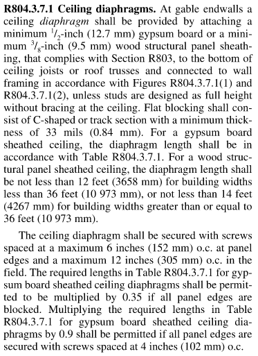
you are correct IRC does require complete load paths, but I'm not sure how it expects non-engineer IRC users to trace loads. I just spent another hour reading thru this and the wood portion is completely silent on ceiling diaphragms, but the cold form portion gives the following guidance, which at first glance seems pretty clear. Good job cold form committee, you get to keep your jobs. Were the cold form provisions added at a later date and maybe based on engineering to some degree? I guess I'm still wondering if it's such a good idea to count on gyp board in tension, but hey it's something.
Screenshot_2024-06-17_120001_arpgxv.png

Screenshot_2024-06-17_112955_cqgego.png

Screenshot_2024-06-17_114510_g6pome.png

Screenshot_2024-06-17_114520_njpeaw.png


XR
if you're in a hurricane region I would not be surprised if your local codes specify requirements for ceiling diaphragms and their connections. vanilla IRC does not.
great point about the perpendicular wall bracing, reminds me of our previous discussion on basement walls. sorry to say this phamENG but I think part of the solution here is to add restrictions like max perpendicular wall spacing to IRC, even if it means the code gets longer.
 
Mike Mike - Well, complete load path is something that's easier for engineers to see (maybe), but this is a pretty well documented flaw that building officials and contractors should be able to see given the abundant literature on the subject. As our rules state "practice in your area of competency", G.C. has something similar, I suspect.

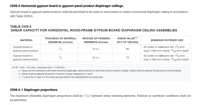
That detail you show for cold formed steel the tie is in tension, I think the gypsum board ceiling is more accurately described as a diaphragm, so it's in shear more than outright direct tension, unless we want to start debating shear as diagonal tension, but a gypsum board is used as a shear wall element, so even if you want to argue diagonal tension, tension-field action, (plate girder), etc, it's still documented to work (*under the test conditions*) and the IBC last I looked did allow a gypsum board ceiling to function as a diaphragm, provided you didn't count the plywood/OSB roof sheathing (which kind of means it won't math out), but it has some recognized capacity in the base code.

The light gage stuff showed up circa 2003, so I suspect there's at least some engineering behind it. Given that the studs are engineered/manufactured to be just crappy enough to be used as substitutes for wood, they may have just calibrated their design to "match" the light frame wood, which puts it in the same rather inauspicious boat as the light frame provisions, "time-tested" without any consistent, documented factor of safety.

You might see some similar diaphragm supplement via the ceiling in the Florida disaster preparation hurricane retrofit materials, as well. I think I've seen that there.
 
The gyp board would be in compression in a positive wind loading. The fasteners in shear.

The case is made for the gyp board acting as a diaphragm for positive wind pressure, but what is holding the wall back from negative pressure?
 
The gyp board acts in tension, compression and shear where the framing runs parallel to the gable unless you have a long line of blocking or struts to act as a sub-diaphragm.
 
Just remember - there's no actual, accepted design guidance for a gypsum diaphragm. So while it may be useful for explaining why some haven't failed, there's nothing to lean on if you use it in a design and it doesn't work quite as well as planned.

lex, no need to say sorry - I wouldn't complain. As long as it's laid out in a sensible and easy to follow manner. Like the WFCM. That's a good example of cookbook house design. And that's what the IRC needs to be. It's not nearly as esoteric as the IBC, but there really needs to be some checklist or flowchart for people to follow through the design to ensure nothing gets missed.
 
phamENG said:
Just remember - there's no actual, accepted design guidance for a gypsum diaphragm. So while it may be useful for explaining why some haven't failed, there's nothing to lean on if you use it in a design and it doesn't work quite as well as planned.

Standard Practice is what protects us in these situations.
 
Whose standard practice? Ours or the builder's?
 
Ours. Since your competition down the street or even in the next town is doing the same thing, you are protected.
 
phamENG said:
Just remember - there's no actual, accepted design guidance for a gypsum diaphragm. So while it may be useful for explaining why some haven't failed, there's nothing to lean on if you use it in a design and it doesn't work quite as well as planned.

Huh?

It's in the code, it's just not viable because it's prohibited to use both the gypsum diaphragm from the ceiling and the structural panel above in combination, footnote a). They both have similar stiffness, so they both get involved in reality, it's just not permitted in the code.

( I don't use these in the design sense, I mention this because they have similar stiffness). They gypsum ceiling is not absolutely along for the ride, it's part of the stiffness. We just don't use it, typically, in a structural design because there's something 3-4-5x stronger nearby, the plywood/OSB roof deck.

2021_IBC_2308.6_Horizontal_Gypsum_Diaphragms_mvxmwe.png

Source: 2021 International Building Code

phamENG said:
... No need to say sorry...

Not sure what you mean about the "sorry" I apparently say that a lot more than I realize. I searched but don't see where we are on that one.

Edit: added code link.
 
Whoa. Where did that come from? What version of the IBC is that?

Never mind. It's in my code, too...but in a chapter I've never bothered to look at. Because why would I? Good to know it's there, though I have no intention of using it.
 
It's not the most useful provision in the history of man, particularly with footnote a, if you read it.....
 
It's as though it's designed specifically for the gable end bracing condition we're talking about. Wind loads on all other surfaces will go to the roof diaphragm - just the stuff acting around the hinge would go into this one.

I still don't like it, though. But my distaste for structural gypsum is well document on this forum.
 

Part and Inventory Search

Sponsor