Continue to Site

Eng-Tips is the largest engineering community on the Internet

Intelligent Work Forums for Engineering Professionals

  • Congratulations IDS on being selected by the Eng-Tips community for having the most helpful posts in the forums last week. Way to Go!

What is a "datum line"? 6

Status
Not open for further replies.

Burunduk

Mechanical
May 2, 2019
2,454
Hello.
I have a theoretical question about datums. According to ASME Y14.5-2009 a datum is:

"a theoretically exact point, axis, line, plane, or combination thereof derived from the theoretical datum feature simulator."

I have encountered all of the types of datums listed, except "line". Didn't find an example in the standard either. Perhaps someone on this forum can help - what is a datum line? What is the corresponding datum feature and datum feature simulator from which it is derived?

Thank you
 
Replies continue below

Recommended for you

However, unfortunately, based on my experience I can envision a case that the vendor or manufacturing department might insist on changing the drawing so that the right edge is utilized as the measurement origin, because the easiest solution for them technically for inspection might be supporting the part by the edge against a flat face in a fixture which is perpendicular to datum plane B and measuring from it. The downside of it is that the edge is probably not a functional feature in assembly and not very reliable for DOF constraints.

A datum feature/datum feature simulator or even a Datum Reference Frame is not the same thing as a measurement origin. Per our discussion above, the measurement origin can be anywhere - as long as it is consistent between measurements. These can be coincident, however they do not have to be.

I would recommend against using a sharp edge like this unless absolutely necessary, especially if it is not actually a functional feature. I would say it will constrain DOF reliably, however unless strictly controlled it likely will not result in repeatable measurements. This is because of edge break requirements (ie; deburring), or if unbroken with burrs/flashing, and unless extreme care is taken - contacting the edge on a gauge or any other surface will have an impact on measurement (think dulling of a knife blade). These may not be a concern with wide open tolerances, but definitely something to consider.

If we're playing devils advocate though, I'd be interested to know more about the application - an obtuse angle significantly greater than 90deg (in this case 135deg) may be difficult to reliably position on a physical gauge as well (though I expect measurement with a CMM would be relatively simple), perhaps this isn't even a functional surface. I don't know because more information was not provided.

I agree, but the same argument (that measurement equipment cannot touch theoretical features) can be used against utilizing the datum plane from which basic dimension 99.03 is given, which is comparable with the "Third datum plane" from fig. 4-4 in the 1994 standard. Nevertheless, the fixture that is needed to construct for inspection of the part in fig.4-4, making the plane in question not theoretical, might be simpler than the one that is needed to utilize the vertical plane at the intersection of B and C at the part in question.

I don't quite follow. I assume you mean something about creation of a theoretical datum plane which is not coincident to the datum feature - this is not the "same" argument. The creation of the theoretical datum planes is just that - theoretical, what truly matters is the constraint of said datum planes in relation to the physical datum features/simulators.

My perspective with this was like Burunduk's that, in practice, it might be easier to measure from the edge even if it's not perfect.

It might be "easier" to create a fixture, but as I pointed out, comes with its own host of issues. Can you tell us more about this application and how it assembles? I am wondering if C is even a functional surface.

But I guess that's a decision for the manufacturer and I should just keep to the standard.

I would vehemently disagree. The manufacturer should not be utilizing this edge as a datum feature/target if it is not specified as such on the drawing.

Edit - several spelling/grammar mistakes. Something something mondays....
 
I should probably clarify my previous post and note that when I said that a sharp edge is not reliable in constraining degrees of freedom I mostly meant that it won't constrain the DOF in the same way as the flat surfaces would in assembly (and I am assuming here that the flat surfaces constrain the part in the application assembly). The meaning of it is that the part might end up oriented differently than the design intent probably imposes.

chez311 said:
I don't quite follow. I assume you mean something about the creation of a theoretical datum plane which is not coincident to the datum feature - this is not the "same" argument. The creation of the theoretical datum planes is just that - theoretical, what truly matters is the constraint of said datum planes in relation to the physical datum features/simulators.

I will clarify. The tolerance zone for the right hole should be located 99.03 from a theoretical plane at the intersection of datum planes B and C, in a direction perpendicular to that theoretical plane and parallel to plane B. Suppose this direction is the X coordinate. During the inspection of the RFS position tolerance, they will want to report the X coordinate of the measured hole axis and later see if it is within the tolerance zone which is located 99.03 at X.
I remind that your suggestion was:
chez311 said:
Your measurement equipment and gauging cannot touch theoretical features - it would contact and measure the planar face of datum feature C and that would be perfectly acceptable.
I am sure you meant to say that the measurement equipment will touch the datum feature simulator of datum feature C. Regardless, my point was that since using the angled datum feature simulator C as the measurement origin (as I understand from your suggestion above) would be troublesome as it is not perpendicular to the X coordinate axis, then essentially to validate this dimension position tolerance conformance they must "touch" a "theoretical" plane of the datum reference frame, derived from datum feature simulators B and C - not even a physical datum feature simulator. That's why I said that the argument that "the measurement equipment cannot touch theoretical features" can be used against the scheme we both consider as the correct one.
 
I mostly meant that it won't constrain the DOF in the same way as the flat surfaces would in assembly (and I am assuming here that the flat surfaces constrain the part in the application assembly). The meaning of it is that the part might end up oriented differently than the design intent probably imposes.

I would tend to agree with this. Add this to the list of reasons that an edge like this shouldn't be utilized as a datum feature/target. See below - this edge is actually defined by the intersection of two surfaces and as such is affected by variations in both. In addition to the reasons I mentioned, this would impose additional unexpected variation during measurement. The figure is simplified, but the concept translates - apologies for the rough nature, I drew it up quickly. Note that a 2deg inclination of the top surface has correlated directly to a 2deg inclination of the edge (*90deg vs 92deg - imagine this to represent the datum target edge C in Yuyu28's example), even though the angle of the surface (*45deg - imagine this to represent the datum feature C in the same example) is unchanged.

ANGLE_INCLINATION_eq76bt.jpg


During the inspection of the RFS position tolerance, they will want to report the X coordinate of the measured hole axis and later see if it is within the tolerance zone which is located 99.03 at X

I'm not intimately familiar with reporting requirements, but I'd be more inclined to say the actual value for the axis would be reported - ie: amount of deviation of the axis from true position which does not involve coordinates or basic dimensions past defining the location of true position. I doubt coordinates would be reported, and even if they were - your measurement origin can be anywhere. Specification of a 99.03 basic dimension in no way locks your measurement origin to that point or any other.

I am sure you meant to say that the measurement equipment will touch the datum feature simulator of datum feature C

No, I meant exactly what I said. Why would you measure the simulator in this case? Your gauge (simulator) will touch the datum feature and your measurement equipment (CMM probe, dial indicator, etc..) will also touch the datum feature.

Regardless, my point was that since using the angled datum feature simulator C as the measurement origin (as I understand from your suggestion above) would be troublesome as it is not perpendicular to the X coordinate axis, then essentially to validate this dimension they must "touch" a "theoretical" plane of the datum reference plane, derived from datum feature simulators B and C - not even a physical datum feature simulator

Again, distinction between a datum feature, datum feature simulator, datum reference frame, and measurement origin. None of these are interchangeable - any point can be used as the measurement origin. I'm not sure why you think this would create an issue, the basic dimensions define the theoretically exact location/orientation of the tolerance zone. It is not the dimension which is being validated, but that the feature falls within the specified tolerance zone. Any equivalent combination of basic dimensions/origin can be utilized without affecting the result.

*Added angle references to tie into my figure
 
chez311 said:
I'm not intimately familiar with reporting requirements, but I'd be more inclined to say the actual value for the axis would be reported - ie: amount of deviation of the axis from true position which does not involve coordinates or basic dimensions past defining the location of true position. I doubt coordinates would be reported, and even if they were - your measurement origin can be anywhere. Specification of a 99.03 basic dimension in no way locks your measurement origin to that point or any other.

The actual value is the "bottom line" but as far as I know often the inspection report for position RFS includes the following columns: the theoretical coordinates of the true position location: for example X and Y, the measured coordinates of the actual axis of the considered feature: X(measured), Y(measured) and finally the actual value, calculated from the difference between the measured coordinates and the true position coordinates. This is done by using the Pythagorean theorem on the differences (which results in the radius) and multiplying by two (which results in the diameter associated with the actual value). As a matter of fact, it doesn't matter if the coordinates are reported or not. Even if only the actual value is reported, measurement of the coordinates of the actual axis is still carried out, hence the need for a reference on which you can master the probe of your measurement device - usually a physical datum feature simulator that can be conveniently used for that - not one that is at some odd angle to the direction of the locating dimensions.

chez311 said:
No, I meant exactly what I said. Why would you measure the simulator in this case? Your gauge (simulator) will touch the datum feature and your measurement equipment (CMM probe, dial indicator, etc..) will also touch the datum feature.

The tolerance zone is fixed relative to the datum feature simulators, therefore when inspection of actual axes/ center planes/ surfaces of considered features is performed, the references for measurements are also the datum feature simulators, not the surfaces of the datum features.
 
X(measured), Y(measured) and finally the actual value, calculated from the difference between the measured coordinates and the true position coordinates.

What is the meaning of (x,y) coordinates of an axis with orientation error*? This does not seem like useful information, even if reported. The actual value (smallest radius, located at true position, which contains the axis) would be the only thing I would think is of interest in that case.

As a matter of fact, it doesn't matter if the coordinates are reported or not.

I would say the same, but because the actual value doesn't care where your origin is. These calculations can take place no matter where the arbitrary origin is taken from, as long as its consistent between measurements, it makes no difference.

usually a physical datum feature simulator that can be conveniently used for that - not one that is at some odd angle to the direction of the locating dimensions.

Convenience does not seem like a good enough reason to change a datum feature from a functional feature/surface to another "nicer" feature/surface. If it cannot be inspected, or inspected reliably that is a different matter - but just because it is not "easy" does not convince me. Of course, every designer is charged with making their own decisions based on part function, cost, tolerances, application, etc.. but that would be my personal stance unless convinced overwhelmingly otherwise.

If we're talking about the example in question, I've already showed several reasons why the seemingly "nice" edge would actually not be preferred - unless your tolerances are wide open, I am of the opinion that appeasing your inspectors in this case would create more problems than it solves.

The tolerance zone is fixed relative to the datum feature simulators, therefore when inspection of actual axes/ center planes/ surfaces of considered features is performed, the references for measurements are also the datum feature simulators, not the surfaces of the datum features.

Thats a fair point. I was however also referring to the fact that the datum features themselves must also be inspected/qualified.


*Edit: Is it perhaps the (x,y) coordinates of the non-location constrained RAME (constrained in orientation only)? *Edit2 - or maybe the non-location constrained "UAME axis containing envelope"? These could be of use in certain instances I guess, but does not translate to actual value calculation. If its not, I'm not really sure whats being reported.
 
chez311 said:
What is the meaning of (x,y) coordinates of an axis with orientation error*?

I've been asking myself the same question. But recording, and usually also reporting the measured coordinates is how I've seen this done and taught in various sources. A few examples are:

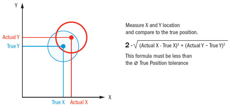
An explanatory figure from gdtbasics.com:
True-Position-Formula_fewuj5.jpg


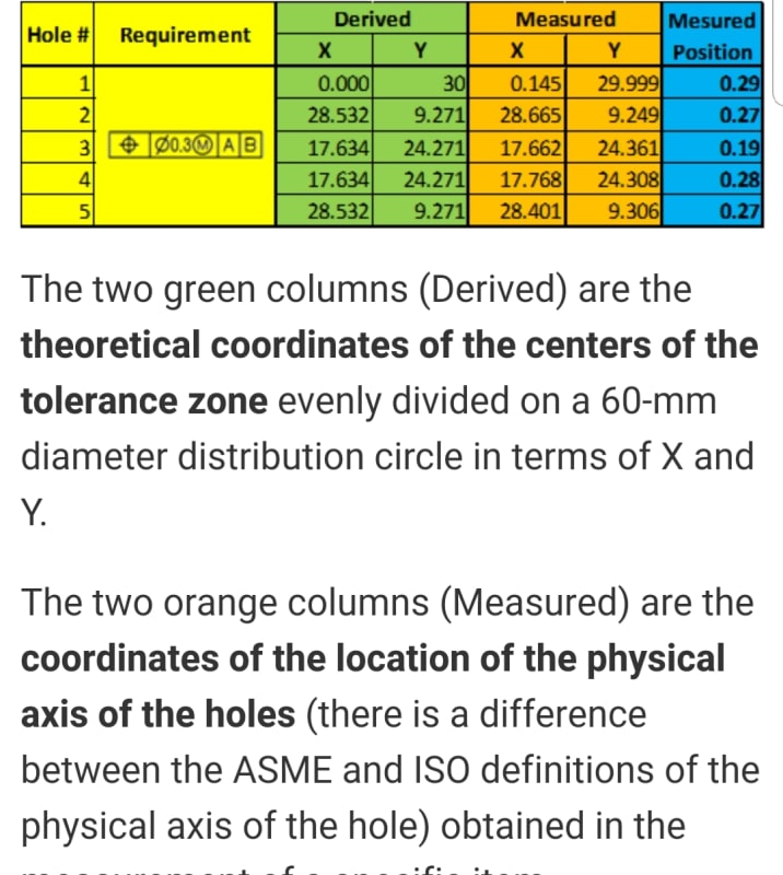
A suggested measurement report from a tip on some other GD&T training website (It can be argued that this source is unreliable as they suggest validation according to axis interpretation for an MMC tolerance specification):
Screenshot_20190910-061221_Chrome_ey0xzr.jpg


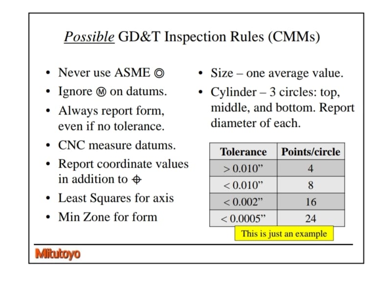
A more reliable source is CMM measurement guidelines from Mitutoyo. Notice the part that recommends/guides to report coordinates in addition to the actual value of position.
Screenshot_20190910-061929_Drive_nktd51.jpg


chez311 said:
the actual value doesn't care where your origin is. These calculations can take place no matter where the arbitrary origin is taken from, as long as its consistent between measurements, it makes no difference.
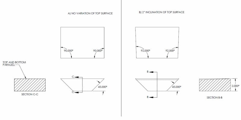
The point was that while datum feature simulator C in YuYu28's figure is good enough to constrain the translational degree of freedom in the horizontal direction (parallel to datum plane B), it is a bad reference to set a zero on, for coordinate measurements in that same direction. Perhaps one could use as a reference a fixed point/line element along this slanted plane simulator, for example at a distance of 130 from the theoretical location of the true position, and set a zero there, but I don't know how practical that is. Perhaps someone with inspection experience can share their insight.
Another option could be to convert the horizontal locating dimension 99.03 to a dimension at the direction perpendicular to the C datum plane. The other locating dimension- 11 is perpendicular to B so the two "coordinate" dimensions for measurement become non-perpendicular. This is probably troublesome too. Even when Y14.5-2009 describes the "Rectangular coordinate method" (7.4.4.1) it specifies that:
"The feature control frames are attached to dimension lines applied in perpendicular directions." I assume that the perpendicular directions requirement is from practical reasons as any coordinate system is based on perpendicular axes.
So the only practical choice left seems to be using an "arbitrary origin" instead, but then - again, you are not avoiding the "inspection equipment touching theoretical features" argument that you brought up. Datum feature simulator C will not be the direct reference. It will be necessary to set a zero on a theoretical origin, one that is not directly tied to a datum feature, i.e. not a datum feature simulator.

Nevertheless, using the physical edge as a measurement origin is not a theoretically valid option, from the reasons we both mentioned. Unfortunately, it is an option that manufacturing might push for in order to avoid complicated gauging (that is according to my experience). It is good for Yuyu28 to be aware of these issues in order to be ready to cope with them.
 
Burunduk, chez311, thank you for your discussion. I can't add anything useful to it but I am learning a lot from your posts. I will let you know what we settle for once the part has been reviewed and released.

I don't like leaving questions unanswered, so...
chez311 said:
Can you tell us more about this application and how it assembles?

My drawing is a simplification of a component of a gyrocopter's teeter mechanism. This beam is attached to the teeter hub only by two bolts on the toleranced holes. There are also another two (not drawn) holes at the extremes of the beam through which two other rotating parts attach. The part doesn't assemble to anything else.

Again, I have no previous experience with GD&T so my idea of using datum target C was just a wild one based on your previous discussion. I will go forward with the inclined plane as datum feature C and see what the reviewers say.
 
Yuyu28,

Holes not shown at which extremes, through which surfaces and in what direction? Maybe you could do a quick rough sketch or markup which shows these holes and where the Mating components attach.

What I'm really trying to determine is whether anything actually touches the inclined surface C and whether or not it's actually a functional surface during assembly or part function.
 
chez311,

The not shown holes are positioned in the same direction and through the same surfaces as the ones shown. Their axes are perpendicular to datum feature A and located at the sides of the beam farthest from the symmetry plane of the part, roughly below the leader of datum C symbol.

Neither of the datum features A, B or C touches any other part, so I wouldn't consider them functional surfaces.
 
This beam is attached to the teeter hub only by two bolts on the toleranced holes. There are also another two (not drawn) holes at the extremes of the beam through which two other rotating parts attach.

Neither of the datum features A, B or C touches any other part, so I wouldn't consider them functional surfaces.

From your previous statement, it seems like this component mates to the "teeter hub" and "two other rotating parts" to at least the flat face datum feature A, clamped to this surface through the bolt holes indicated. Am I reading your first statement wrong and it actually floats in space, only touching bolts through the holes indicated as your second statement would suggest? This seems unlikely.
 
Yuyu28,

Anyway, it seems like my initial hunch was correct - that your surface C is not a functional surface. Your datum features should always be driven from part function and assembly condition, with rare exception.

If the part bolts through the 2x holes shown to clamp the part to the surface datum feature A then my recommendation would be to designate this surface as datum feature A (same as shown) and the pattern of 2x holes as datum feature B. The rest of the features/surfaces on the part can be held to |A|B|. Since I assume these are clearance holes, it may be recommended to utilize MMB boundary condition |A|B(M)| for the holes to allow for datum shift instead of RMB. MMC would also be recommended for the position tolerance on the holes.
 
Yuyu28, you mentioned it is a simplification, it must be super-simplified. How is the part mounted to the teeter hub? You mentioned the datum feature A, B, C surfaces don't contact anything so it isn't friction either. It is a rotating part - can it be constrained only by the bolts that go through the clearance holes? I agree with chez311 - seems unlikely. No other locating features but the holes? Or should there be pins that fit tightly in those holes?
 
Burunduk,

The GDnT basics example, as well as many I've seen in similar basic explanations of position deviation, shows an axis with no orientation error. This is fine for introduction/teaching of the concepts. I'm going to skirt around the second example based on their questionable distinction of derived vs. measured, as well as definition of the "physical axis" which is paradoxical. The note in the Mitotoyo presentation is interesting though. After some thought, I would assume that the (x,y) coordinates would be of the axis of the non-location constrained "UAME axis containing envelope". This, in comparison to the diameter of said envelope would give us some idea of axis orientation vs location error. That said, I would personally prefer to see these coordinates provided from each feature's true position ie: (Δx,Δy) instead of from some arbitrary measurement origin. Additionally, we could also envision this difference as comparison of the size of the location vs. non-location constrained "UAME axis containing envelope" (the former of which would be the position actual value) - though use of coordinates may be more intuitive for most people to visualize position error.

Perhaps one could use as a reference a fixed point/line element along this slanted plane simulator, for example at a distance of 130 from the theoretical location of the true position, and set a zero there

Or maybe another vertical simulator artifact (i use the term simulator here somewhat generously since it would not actually contact the part) which is of a fixed distance from the angled simulator, that does not contact the part (this may be a no-no, just spit balling here). Or if practical, direct measurement of the datum feature and establishing the simulator virtually. I have to imagine an inclined feature is well within the realm of the possible, and while perhaps more difficult than a nicely perpendicular feature should not confound a capable quality department.

Another option could be to convert the horizontal locating dimension 99.03 to a dimension at the direction perpendicular to the C datum plane. The other locating dimension- 11 is perpendicular to B so the two "coordinate" dimensions for measurement become non-perpendicular. This is probably troublesome too.

Changing around your basic dimensions will have no impact on the result. The feature can be defined in any infinite combination of equivalent basic dimensioning schemes, the only real impact may be readability and some assumptions/inferences a person reading the print might make.

Nevertheless, using the physical edge as a measurement origin is not a theoretically valid option, from the reasons we both mentioned. Unfortunately, it is an option that manufacturing might push for in order to avoid complicated gauging (that is according to my experience). It is good for Yuyu28 to be aware of these issues in order to be ready to cope with them.

Here we agree, doubly so since it has been determined that the inclined feature/edge are neither functional features.
 
To clarify what I meant by "maybe another vertical simulatorartifact [...] which is of a fixed distance from the angled simulator" I was referring to something like a tooling ball ( or similar feature which can be easily probed.

You might say this falls under your below statement

It will be necessary to set a zero on a theoretical origin, one that is not directly tied to a datum feature, i.e. not a datum feature simulator.

I would say it is not. The datum feature would still contact a physical simulator, and the distance to the tooling ball (or similar artifact) would be known and fixed, and could be validated. The measurement origin/zero can be anywhere as I've said several times - there is no requirement for it to be coincident with the surface of the datum feature/simulator. It would be up to the tooling designer/manufacturer to ensure their tolerances of this artifact is within acceptable limits. I believe such features are sometimes utilized to qualify nests of multiple parts. Of course if the tolerances for this method are unacceptable for the application, then either the simulator itself or the datum feature must be probed.
 
chez311 said:
Or if practical, direct measurement of the datum feature and establishing the simulator virtually. I have to imagine an inclined feature is well within the realm of the possible, and while perhaps more difficult than a nicely perpendicular feature should not confound a capable quality department.

It doesn't really matter how the slanted datum plane C is simulated, be it virtually or physically, a determined single distance value from the entire simulator to the considered hole axis or the true position location in the direction parallel to plane B is nonexistent. The other "vertical simulator" which you mentioned is the most probable option I see, even though it is somewhat detached from the actual part geometry (it is related only to the datum feature simulators A B and C which are basically constrained to each other regardless of the part as produced).

chez311 said:
Changing around your basic dimensions will have no impact on the result. The feature can be defined in any infinite combination of equivalent basic dimensioning schemes, the only real impact may be readability and some assumptions/inferences a person reading the print might make.

I didn't mean changing the dimension on the drawing, but converting it to a more practical "dimension" (unambiguous location of true position relative to the datum feature simulator) for coordinate measurement. Sorry for not being more clear on that.

 
It doesn't really matter how the slanted datum plane C is simulated, be it virtually or physically, a determined single distance value from the entire simulator to the considered hole axis or the true position location in the direction parallel to plane B is nonexistent.

I didn't mean changing the dimension on the drawing, but converting it to a more practical "dimension" (unambiguous location of true position relative to the datum feature simulator)

You've sort of lost me. Is the "dimension" in quotes or the distance value in bold supposed to refer to something other than the dimension on the print? If either refers to the basic dimensions on the print, see my response on (10 Sep 19 14:12) regarding equivalent basic dimensioning schemes - there is no requirement for a "single distance value" from the "entire" simulator, *though such a dimension could be included. If you are talking about something else, I'm not sure what you're referring to. Regardless, use of an inclined feature is not ambiguous.

*Edited for clarity
 
chez311, both in the bolded part of your quote and when I referred to a "dimension" in your second quote I was talking about measurable distances along coordinate system axes between datum feature simulators and either true position locations or actual derived feature axes (and in the context of derived feature axes, whatever the effect of orientation error might be, we can't avoid the discussion of measured location values within a datum reference frame, or practically speaking the coordinate axis system of the inspection set up).
The above mentioned measurable distances are not the same thing as the dimensions on the print. I agree about the possibilities of equivalent basic dimensioning schemes and the fact that the basic dimensions on the print do not impose specific measurement origin or coordinate axes directions. That is why I suggested that the 11 and 99.03 basic dimensions locating the true position of the hole can be converted (even for measurement purposes only, and not necessarily on the drawing) into distances of 11 and some other distance in a direction perpendicular to datum feature C, replacing the value of 99.03 - which can't be translated into a measurable distance in the same direction (parallel to B) when the origin of measurement is datum feature simulator C (and not some arbitrary local element on it). This, however, introduces another issue of non-perpendicular coordinates as I mentioned. I agree that there is the arbitrary measurement origin that can be utilized such as your suggested tooling ball, and as long as a fact is acknowledged that this is not a simple and straightforward solution and not the same as measuring directly from the inclined datum feature simulator C, I have no issue with it. My initial point was that I perfectly understand what drove Yuyu28 to try and utilize the edge as the origin for measurement, because as problematic and incorrect as it is, it is more "dimensionally definable", so to speak, in the horizontal direction of the drawing view to the positioned hole. And he should be aware of the possibility that the manufacturer might prefer it or ask for it to simplify gauging (supporting the part by the functionally irrelevant edge on a vertical face of a simple fixture constructed of nothing but 3 perpendicular plane surfaces). But obviously, he should also be aware of the consequences of such practice, to resist it effectively.
 
I suggested that the 11 and 99.03 basic dimensions locating the true position of the hole can be converted (even for measurement purposes only, and not necessarily on the drawing) into distances of 11 and some other distance in a direction perpendicular to datum feature C, replacing the value of 99.03 - which can't be translated into a measurable distance in the same direction (parallel to B) when the origin of measurement is datum feature simulator C (and not some arbitrary local element on it).

This all happens behind the scenes (calculations done by CMM software) and in no way should hamper the selection of inclined face C as a datum feature. Assuming that the relationship between the datum feature/simulator and the tolerance zone has been properly defined with basic dimensions, the rest is trigonometry.

This, however, introduces another issue of non-perpendicular coordinates as I mentioned.

Again, trigonometry. Not really clear on why you believe this would be an issue. This would be no different than the inverse - measurement of an inclined face from a set of datum features which are not parallel/perpendicular to it.

I agree that there is the arbitrary measurement origin that can be utilized such as your suggested tooling ball, and as long as a fact is acknowledged that this is not a simple and straightforward solution and not the same as measuring directly from the inclined datum feature simulator C, I have no issue with it.

I don't think I ever said it was. I think you'll find we agree here.
 
chez311, I agree that many things such as datum plane simulations, trigonometrical conversion of distances, etc can happen behind the scenes, but as far as I know, those conversions and everything else may require some demanding and time-consuming programming and set up preparation work.
Sometimes a CMM is not available and everything needs to be carried out by more traditional metrology work. That is while manufacturers are not always enthusiastic to invest time in inspection. While it shouldn't be at the expense of specifications driven by part function, it may be useful to bear in mind manufacturing and inspection considerations.

chez311 said:
I don't think I ever said it was. I think you'll find we agree here.

chez311 (Automotive)6 Sep 19 20:35 said:
To position the holes horizontally, I need some datum plane perpendicular to the plane of the view

All you really need is a datum feature which constrains translation in the direction of interest...

...Your measurement equipment and gauging cannot touch theoretical features - it would contact and measure the planar face of datum feature C and that would be perfectly acceptable...

The second part of your quote is where I thought you were oversimplifying things... Depending on the available measurement equipment and process the meaning of the lack of a directly derived (from the drawing) vertical datum plane might be that the probe will be contacting an auxiliary component such as the tooling ball (and not datum feature/simulator C)- a purely theoretical and virtual entity as far as the drawing is concerned. But perhaps I didn't interpret your statement correctly.
 
datum plane simulations, trigonometrical conversion of distances, etc can happen behind the scenes, but as far as I know, those conversions and everything else may require some demanding and time-consuming programming and set up preparation work.
Sometimes a CMM is not available and everything needs to be carried out by more traditional metrology work. That is while manufacturers are not always enthusiastic to invest time in inspection.

Its up to the inspection department to ensure they have correct equipment for the application. I agree that this should be taken into consideration and not specify overly tight or complex requirements in an application which does not require it, but ultimately if the design requires it the inspection department has to figure it out, and if its not possible or is cost prohibitive then that is a conversation which has to happen. There are certain requirements that are not practical or even possible, especially in large volumes, to inspect with traditional equipment. There is also requirements that are easier for traditional equipment/hard gauges to handle than a CMM - think MMC/MMB.

The second part of your quote is where I thought you were oversimplifying things... Depending on the available measurement equipment and process the meaning of the lack of a directly derived (from the drawing) vertical datum plane might be that the probe will be contacting an auxiliary component such as the tooling ball (and not datum feature/simulator C)- a purely theoretical and virtual entity as far as the drawing is concerned. But perhaps I didn't interpret your statement correctly.

I tried to clarify this in my post (10 Sep 19 15:21) but I may not have done a good enough job.

My initial post (6 Sep 19 20:35) was trying to assert that the location/creation of the theoretical datum plane(s) is not really important. Its constraint of the datum features/simulators which is important - any theoretical datum planes/points/lines result from contact with these physical features. My point in saying "Your measurement equipment and gauging cannot touch theoretical features" is the same reason we don't specify centerlines, centerpoints, lines at the intersection of two planes, or other theoretical geometry as datum features - this theoretical geometry is derived from physical features, not the other way around.

In reference to probing a tooling ball or similar artifact - this is only a valid reference because of the contact of the simulator with the datum feature inclined face C. It is arbitrary, but not theoretical as it is a physical feature of a known, fixed distance to the simulator. In an ideal world this would be the same as probing the simulator itself - however as we do not live in an ideal world, it is up to the quality department to determine whether the errors induced by this or other methods are acceptable. I guess we could argue about the semantics of that and what you mean by "a purely theoretical and virtual entity as far as the drawing is concerned" however I wasn't really intending to validate this as an inspection method. My only point was only to reinforce my expectation that a quality department should be able to handle such a specification with a multitude of methods.
 
Status
Not open for further replies.

Part and Inventory Search

Sponsor