Continue to Site

Eng-Tips is the largest engineering community on the Internet

Intelligent Work Forums for Engineering Professionals

  • Congratulations SDETERS on being selected by the Eng-Tips community for having the most helpful posts in the forums last week. Way to Go!

What is a "datum line"? 6

Status
Not open for further replies.

Burunduk

Mechanical
May 2, 2019
2,483
Hello.
I have a theoretical question about datums. According to ASME Y14.5-2009 a datum is:

"a theoretically exact point, axis, line, plane, or combination thereof derived from the theoretical datum feature simulator."

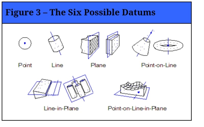
I have encountered all of the types of datums listed, except "line". Didn't find an example in the standard either. Perhaps someone on this forum can help - what is a datum line? What is the corresponding datum feature and datum feature simulator from which it is derived?

Thank you
 
Replies continue below

Recommended for you

Belanger,
I am curious about the change you mentioned in the 2018 definition. According to Nonmandatory Appendix A in the 2009 standard, the term "true geometric counterpart" was replaced in that revision by "datum feature simulator". Was it reversed back to the older terminology in the new standard?

chez311, CheckerHater, greenimi,
I have difficulty with the suggestion that the datum line mentioned in the definition of the term datum is the datum target line. I think that datum targets are closely related to the concept of datum features, less so to datums. Datum targets designate selected portions of datum features, and much like complete datum features, associated with simulators which are used to derive datums further down in the process. It seems that mentioning a line related to the datum target concept as a type of datum is much like mentioning a cylinder related to the datum feature concept as a type of datum. Am I mistaken?
 
Burunduk, yes that does seem to be the case. In the 1994 edition, paragraph 1.3.3 states that a datum is "a theoretically exact point, axis, or plane derived from the true geometric counterpart of a specified datum feature." And that had remained unchanged from the 1982 edition.

Gee, those committee meetings must be fun if they get to debate stuff like this.

John-Paul Belanger
Certified Sr. GD&T Professional
Geometric Learning Systems
 
Yes, swapping terms back and forth at the committee sounds fun. Less fun for the standard users though.

Interesting to note: according to the quote you provided, "line" wasn't included in the 1994 or earlier versions. I wonder what it was added for, especially since no examples were provided.
 
Burunduk and Belanger,
Next week is the committee meeting, so good opportunity to sit in one of these public meetings.
Take a pilow or have a strong coffee ready.


--------------------------------

Y14 SPRING 2019
Date: 06 – 10 May 2019
Location: Minneapolis, Minnesota
Venue: Hilton Minneapolis
1001 Marquette Ave
Minneapolis, MN
55403
 
Has anyone "found" a case-study example where a datum line "exists"? I having trouble finding an example.

Certified Sr. GD&T Professional
 
Here is what my search on the web produced so far:
20190506_180336_vqyrwl.jpg

This is from a 2008 article by William Tandler:All Those Datum Things
The article was based on the 1994 standard, where "line" was not part of the definition. In the article and the figure, it represents an axis. But, since "line" was deliberately added in the 2009 definition, right next to "axis" which was already there, it doesn't seem reasonable that the newly added (in 2009) "line" has the same meaning as in the article (axis). It would be a bad idea to list two different terms with the same meaning in the same definition.

Not sure what it adds to the discussion but I thought it has a place here anyway. My question remains open.
 
Burunduk:

Trying to find an example: I am brain-storming a "line" datum feature as maybe the corner at the intersection of two perpendicular planes - a line - on the sides of a part that would stop the rotation of the two planes that intersect on a datum axis (from a cylindrical feature on the part). The symbology and interpretation would be challenging and might require notes. Let me contemplate this some more ... but my best at this point.

Certified Sr. GD&T Professional
 
mkcski, I read your post and took another look at the figure I posted: it must be the "line in plane"! Like you said an intersection of 2 planes, but not necessarily perpendicular ones. Seems like a flat taper datum feature creates a datum centerplane and a datum (intersection) line. The answer was in front of me and I missed it. Thank you for the clue!
 
Burunduk: I'm not sure how you would apply datum feature symbols to identify the 'Line in plane" you mentioned above.

Please realize that datums features must be physical and the intersection of two planes - the edge - in my example is NOT a physical feature - I dare you to find the "edge" - hahaha. That's why I said "The symbology and interpretation would be challenging and might require notes." It may be a bad example as it pushes GDT to the limit.

Certified Sr. GD&T Professional
 
Do datum features really need to be physical? For instance the axis of a cylindrical tube is not necessarily "physical", but would be a valid datum. That said I'm not quite sure the correct way to physically establish that line datum in this, I'd need to give some more thought.

 
ifw618:

I suspect you may be missing some of the subtle differences in the "datum" terminology;

This is greatly simplified for the Standard but: There are datums, which are perfect. There are physical (imperfect) datum features that are on the part. There are physical datum feature simulators in the processing equipment (in the shop) - machine tools, surface plates, etc. The physical datum features come in contact with the physical simulators to "simulate" the perfect datum.

A planar datum feature establishes a perfect datum plane and is simulated by a plane in the shop - notice plane, plane, plane - easy to grasp

However a cylindrical datum feature establishes a perfect datum axis AND always two perpendicular planes interesting at 90 deg on the axis and can be simulated by the center of a machine tool spindle - a line element like an axis.

A width datum feature - two parallel planes - a keyway for example - establishes a perfect datum center-plane and can be simulated by the center of a machine tool spindle - a line element like an axis.

You might want to review figure 4-3 in 2009.


Certified Sr. GD&T Professional
 
lfw618 said:
Do datum features really need to be physical?
Yes. They do.

lfw618 said:
For instance the axis of a cylindrical tube is not necessarily "physical", but would be a valid datum

Again, the datum FEATURES shall be identifiable. Your "axis" or datum axis is the axis of a datum feature simulator established from the datum feature.


Datum target lines, as discussed before are good examples, and if 4-47/2009 is considered, then the V-shaped simulator is established from 2 datum target lines.
The text goes further and explained the procedure/ drawing indication if V-shaped tangent plane is required.

So, in my opinion, a clear distinction is made on datum target line versus tangent plane V-shaped.

"4.24.5 Establishing a Center Plane From Datum Targets
Figure 4-47 is an example of a V-shaped datum feature
simulator established from two datum target lines.
In the front view, datum targets B1 and B2 are located
relative to datum targets A1 and A2 with a basic dimension
and shown as datum target lines. If a tangent plane
V-shaped datum feature simulator is required, B1 and
B2 would only be shown in the top view."


Ok, yes I see that I did not have the exact terminology correct. Looking back I think what I meant, was that the actual datum would be a theoretical line the same way the axis of a cylinder is a theoretical line. The datum feature would be that "v" which would be a physical feature to derive your datum from. Although it looks like that would derive a center plane and not a line. I will review 4-3 and 4.24.5.
 
greenimi:

Just a comment for consideration:

As opposed to the by-default full-feature contact, my assumption is that datum targets revise the contact with the datum feature to only those "places".

Unlike figure 4-53 where the optional datum feature symbols are shown, figure 4-47 does not show datum feature symbols. Based on the line-contact with the exterior (OD) of the boss, datum feature B is the OD, and the datum symbol would attached to OD making it a cylindrical datum feature B. The datum would then be the axis (where X-Y are shown on the drawing intersecting).

I am confused by your reference to the 4.24.5 statement that "datum target lines." If you agree with my discussion above that Datum B is the axis of the boss, then the "datum target line" is not a "datum line" as the OP is trying to understated.

Certified Sr. GD&T Professional
 
mkcski,

Let me ask you two questions:
- In Chez311's embedded picture posted on 2 May 19 14:12, what is the datum target line?
- Why in 4-53 datum feature symbol A and B are optional? In other words, how the meaning would change if the datum feature A and B wouldn't be shown?

Depending on the number of planes established by higher precedence datums, secondary and tertiary datum axes may establish zero, one, or two theoretical planes.
 
mkcski said:
I'm not sure how you would apply datum feature symbols to identify the 'Line in plane" you mentioned above.

If you are referring to the case with the flat taper than I would suggest:

Option #1: controlling both sides with a single profile feature control frame and two leaders from that feature control frame to the angled surfaces of the taper. The datum feature symbol attached beneath the profile feature control frame.

Option #2: attaching datum feature symbol A to one side, B to the other. The datum(s) ( combination of center plane and a line) should be derived from the |A-B| simulator.

Both options require the basic angle of the taper to be specified.
 
I am glad fig. 4-47 was brought up as it is an interesting one.

mkcski said:
Based on the line-contact with the exterior (OD) of the boss, datum feature B is the OD, and the datum symbol would attached to OD making it a cylindrical datum feature B. The datum would then be the axis (where X-Y are shown on the drawing intersecting).

To establish a datum axis B the datum feature simulator, or datum target line simulators, in this case, need to make contact with the datum feature at opposed points - which is not possible here. My interpretation of this figure is that the combined datum B consists of two datums 1.datum plane through the intersection point of the two datum target lines - which is a 2.datum point to which basic dimension 40 is given. This plane (#1) is also basically oriented at 90° to datum A, and 45° to each of the datum target lines simulators, and is coincident with the shown X-axis of the datum reference frame.
 
Guys:

I am not ignoring your questions. I have a hot estimate to complete today. I will respond ASAP. Sorry

Certified Sr. GD&T Professional
 
Greenimi:

Let me try to respond to your questions from your May 6, 2019 post:

“In Chez311's embedded picture posted on 2 May 19 14:12, what is the datum target line?” There aren’t’ any because there are no datum target symbols. I am really trying to make a distinction between the contact with the datum feature (true geometric counterparts, simulators, targets) and the datum – the origin of measurement – itself. I believe the term “datum target (that is a) line” is a refinement of term “datum feature symbol”. By default, the “datum feature symbol” requires “full” contact with the datum feature, whereas using the “datum target symbol” limits the contact to selected portions of the surface. Looking at figure 4-47 – the targets B1 and B2 define the limited contact with the datum feature’s surface (a cylinder) by lines, but the (perfect) datum is the axis at the center of the boss (as determined by partial contact with the surface at the targets).

“Why in 4-53 datum feature symbol A and B are optional? In other words, how the meaning would change if the datum feature A and B wouldn't be shown?” The meaning would not change, because per paragraph 4.24.1 last sentence, the specifying the datum feature symbol is optional. But in my opinion, adding the datum feature symbol, helps clarify the intent.


Certified Sr. GD&T Professional
 
The last sentence of 4.24.1 is :"The datum feature itself may be identified with a datum feature symbol as shown in Fig. 4-53 or by using the datum reference frame symbol as shown in Fig. 4-54."

I admitted before on this forum, I do not understand fig 4-54. For my life I do not know the fine details of this figure. I see that a datum reference symbol (axes X, Y and Z) are shown and in fig 4-53 are not.
Should I understand that, since datum feature symbol A and B are optional in 4-53, in the case of them missing, the drawing is incomplete (because the axes identification is not shown)?


mkcski said:
“In Chez311's embedded picture posted on 2 May 19 14:12, what is the datum target line?” There aren’t’ any because there are no datum target symbols

Then why the picture is titled datum target line? And the applicable paragraph is 4.24.3 and has the title "datum target Lines"

Men, this standard is really confusing.


Status
Not open for further replies.

Part and Inventory Search

Sponsor