Continue to Site

Eng-Tips is the largest engineering community on the Internet

Intelligent Work Forums for Engineering Professionals

  • Congratulations KootK on being selected by the Eng-Tips community for having the most helpful posts in the forums last week. Way to Go!

What is the difference between torsion & minor axis bending? 3

Status
Not open for further replies.

MelBWasHere

Structural
Oct 13, 2022
6
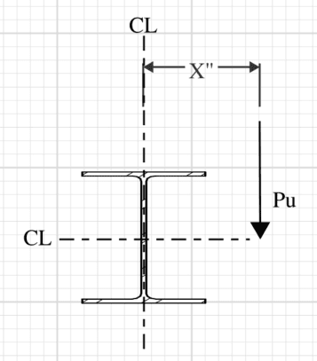
Say I have a wide flange beam in a simple span condition, no lateral support of any kind.
I apply a point load "X" inches away from the beam centerline at the midspan (so an eccentric point load).
Would this loading condition be considered torsion or minor axis bending? I believe it to be torsion after reading AISC design guide 9 but a friend of mine insists it's minor axis bending.
Which is it? Maybe I'm an idiot & need to go back to school (I will be this fall for my master's, lol), but figured I'd ask here to get more thoughts.
 
 https://files.engineering.com/getfile.aspx?folder=fadad2e5-c158-4d07-9988-7a51061471cd&file=Screenshot_2024-06-06_112958.png
Replies continue below

Recommended for you

Well, I would ask your friend to draw a free-body diagram.
 
if the load is vertical, then I'd say you are right.

if the load is horizontal (in-plane with the beam), then I'd say your friend is right.

but, yes, draw FBDs ...
and yes, I couldn't be bother to open you sketch.

"Hoffen wir mal, dass alles gut geht !"
General Paulus, Nov 1942, outside Stalingrad after the launch of Operation Uranus.
 
Screenshot_2024-06-06_112958_mh8rib.png


cripe why can't people just embedded the images rather than attaching them.

anyway, it somewhat depends on how that load is introduced into the beam; there is no attached fitting or other structure shown.

but, that load introduces overall torsion into the bean, assuming the beam is connected at the ends away from the load. the load may also introduce local weak axis bending in the area of the load, depending on the details of the attachment.
 
"cripe why can't people just embedded the images rather than attaching them."

Agreed. More likely for me to actually look at it.
 
Apologies, forgot embedment could be done. I'll do better next time.

Thank you for the helpful comments.

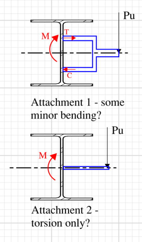
Makes sense that it would depend on the attachment to a degree (blue in the image below, correct me if I'm wrong).

Screenshot_2024-06-06_122521_vf0hns.png
 
I think you are both correct.

With a wide flange beam, a torsional moment will predominantly cause weak axis bending of the top flange and the bottom flange (in opposite directions). It will not cause St. Venant shear stress.

DaveAtkins
 
MelBwashere said:
Would this loading condition be considered torsion or minor axis bending?

Torsion, it's strong axis bending and torsion.

Now, at the risk of making you more confused, I will suggest that your fried was thinking about the "equivalent T analogy" that is used for understanding how a wide flange beam resists torsion and produces "warping stresses" in the flanges.

Take a look at the following thread where I posted some pictures and explanation about the method. Other reference are the AISC design guide and the Salmon and Johnson book on steel design.

 
I think "weak-axis bending" needs to be defined.

If you mean overall member bending moment about the vertical axis (the normal use of the term), then no. In Attachment 1 and 2 there is no weak-axis moment.

If you mean localized out-of-plane bending of the web, then yes, both of those attachments would cause that.

There is certainly torsion in both cases. These cause "warping normal stresses" in the flanges, which is like weak-axis bending, as others in the thread are zeroing in on.
 
MelBWasHere said:
Would this loading condition be considered torsion or minor axis bending? I believe it to be torsion after reading AISC design guide 6 but a friend of mine insists it's minor axis bending.

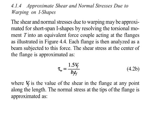
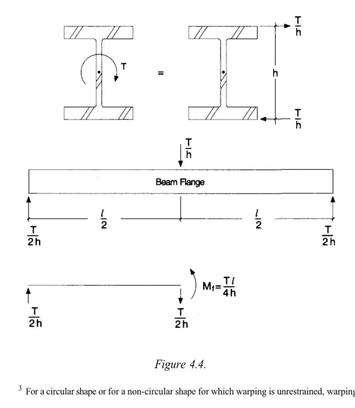
I feel that you are correct. From the perspective of the cross section as a whole, the loading condition causes torsion and no minor axis bending whatsoever. I suspect that your colleague is making reference to a technique that is sometimes called the bi-moment method that acknowledges that wide flange torsional response is dominated by cross section warping which can be approximated by converting the torque into a fictitious, weak axis lateral load. That lateral load is then resisted by the plate elements best suited to resist it by virtue of their lateral stiffness: strong axis (lateral) bending of the flange plates.

The method is described below, as taken from AISC's Design Guide 09 which addresses torsion.

c01_gxa3u9.jpg


c02_nmljef.jpg
 
if your fig 1 picked up the flanges directly then you'd have a better case for "weak axis" bending ... thought really the flanges are resisting in-plane loads (so local strong axis bending of the flange)

"weak axis bending" of the beam implies (to me) a lateral load ... a net lateral load, not a lateral couple.

A natural way for the beam to resist these loads would be differental in-plane shears on the two flanges.

"Hoffen wir mal, dass alles gut geht !"
General Paulus, Nov 1942, outside Stalingrad after the launch of Operation Uranus.
 
yes, agree with rb, weak axis bending requires a net lateral load. Fig 1 and 2 both induce torsion, along with some local web bending, but not weak axis overall beam bending.
 
Both. It applies a torsional force which in open sections is often resolved primarily by minor axis bending (of the beam flanges). One flange bends in. The other bends out. This is why steel beams generally twist far less in reality than stick models say they will.
 
Tomfh said:
Both. It applies a torsional force which in open sections is often resolved primarily by minor axis bending. One flange bends in. The other bends out. This is why steel beams generally twist far less in reality than stick models say they will.
Do we really want to start playing this game?

Next time somebody asks if you load a point in the centre of the beam (loaded in the direction of the major axis) will you also respond by saying it loads up the beam axially by an axial tension force in the bottom flange and axial compression in the top flange? So it is in fact both bending and axially loaded!?

If we are talking about the member as a whole (WHICH WE ARE) there is no minor axis bending.
 
Bending about any axis requires a net shear load (ok, unless it is being loaded with a moment).

For an I beam, strong axis bending puts one flange in tension and the other in compression (and the web carries the shear).
Weak axis bending puts both flanges in bending (and they carry the shear)
Torsion is torsion ... draw the internal shear flows (for all three).

"Hoffen wir mal, dass alles gut geht !"
General Paulus, Nov 1942, outside Stalingrad after the launch of Operation Uranus.
 
Human909 said:
So it is in fact both bending and axially loaded!?

The flanges are loaded axially, producing a net bending force.

In this case here, the flanges experience out of plane bending, which amounts to a torsional couple.

Is the overall section experiencing out of plane bending? Of course not, because the load vector is parallel with the strong axis.
 
I don't like the idea of mixing up wording of minor/major axis bending with out-of-plane/in-plane bending to be honest. In my mind the former only refers to a section (where there will be a stronger and weaker direction), and the latter refers to a particular flat element.

Also, wouldn't the flanges be experiencing in-plane bending if they were forming a torsion couple?

----------------------------------------------------------------------

Why yes, I do in fact have no idea what I'm talking about
 
Out of plane bending is pretty clunky terminology for beam elements. Out of plane bending would be local flange bending, like from a point load.
 
This is a topic bursting with potential for semantic problems. That's precisely why I was so careful with my wording in my previous post.

KootK said:
That lateral load is then resisted by the plate elements best suited to resist it by virtue of their lateral stiffness: strong axis (lateral) bending of the flange plates.

Two decades of experience has taught me not to underestimate the risk of being misinterpreted in technical matters, particularly if I'm abstaining from sketching for the take of time efficiency.

That said, I certainly had no trouble interpreting Tomfh's meaning in his original post. He flat out painted a picture of the (accurate) movement pattern that he was referencing.

Tomfh said:
One flange bends in. The other bends out.

For anyone remotely familiar with torsion in steel, that should suggest opposing, lateral movement of the flanges.
 
To be precise, the applied load is torsion, and there is no minor axis bending.

I was just giving my interpretation of what the friend was referring to.

DaveAtkins
 
Status
Not open for further replies.

Part and Inventory Search

Sponsor