Continue to Site

Eng-Tips is the largest engineering community on the Internet

Intelligent Work Forums for Engineering Professionals

  • Congratulations KootK on being selected by the Eng-Tips community for having the most helpful posts in the forums last week. Way to Go!

What is the positional tolerance of this slot?

Status
Not open for further replies.

tharding247365

Mechanical
Dec 30, 2014
39
Centerline_Block_szftbz.jpg


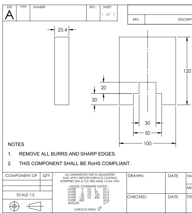
I see this a lot on drawings. This part has no GD&T applied to it, therefore our Sheet Tolerances apply.

Dimensions 30 & 50 are centered on the centerline of the part.

Do we assume the size tolerance IS ALSO the position tolerance, to sheet tolerance.
Do we assume there is "Implied dimensioning to the centerline" and that implied dimension would refer to the sheet tolerance? IE 50 implies 25 from the center, sheet tolerance of 25 dimension?
The features are not fully defined, and require an additional dimension to the centerline of the part, or an edge.


References to standards, or what could help define this would be appreciated! I think this might be something that is overlooked, as I've seen this type of dimensioning on many drawings in the companies I've worked for.
 
Replies continue below

Recommended for you

Drawing states ASME. Would this be different if it were ISO?
 
Yes, it would be different if (for example) ISO2768 (-1, -2) is shown.


I would adventure to say that you are dealing with an incomplete drawing requirements.

The limits of size do not control the orientation or location relationship between individual features.
Features shown perpendicular, coaxial, or symmetrical to each other must be toleranced for location or orientation to avoid incomplete drawing requirements.
 
It does have GD&T on that drawing. There are dimensions to geometry (GD) and tolerances. What it doesn't have is feature control frames or whatever ISO calls them.
 
It is an ambiguous drawing, and it is a super-common error. Since that drawing references ASME Y14.5M-1994, see paragraph 2.7.3 of that document: "Features shown perpendicular, coaxial, or symmetrical to each other must be controlled for location or orientation to avoid incomplete drawing requirements." They then state how that is done (using GD&T symbols for location, orientation, profile, or runout).

It is OK to say that those features are implied to be centered with each other. The issues is that there is no tolerance given for a part this is not made perfect.
 
Status
Not open for further replies.

Part and Inventory Search

Sponsor