Continue to Site

Eng-Tips is the largest engineering community on the Internet

Intelligent Work Forums for Engineering Professionals

  • Congratulations KootK on being selected by the Eng-Tips community for having the most helpful posts in the forums last week. Way to Go!

What Prevents Inadvertent Stress Concentrations or Crack Initiation on most prints? 7

Status
Not open for further replies.

SBlackBeard

Aerospace
Apr 21, 2022
12
I'm a designer - there is a recurring theme with some parts we've seen recently, where there is a sharp step right where we'd least want one. We battle with other departments - they say it meets the print, we say it doesn't.

For example, we might design a bracket with a fillet/blend specifically to avoid a sharp internal corner for stress reasons, but we control the size of the radius or the adjacent flat surfaces with a profile tolerance - say .015 (we use inches). I realize this allows for considerable surface variation (like they draw in the GD&T books!), but we also have a block tolerance surface finish of 63 or 125. Here's an image of it (blue is as-built, grey is as designed):
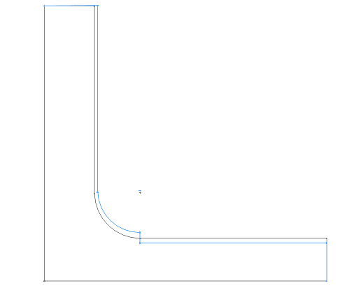
goes_bump_in_the_night_qlts4v.png


You can see there is a step near the root of the fillet. Likely, this was machined with two different tools or from two directions, so I understand HOW it happens. At prior jobs, quality would have rejected or reworked the part. At the current job, Quality says "because the step is within the surface profile tolerance, it meets print."

I originally thought block tolerance surface finish of 125 Ra should cover it. I then thought maybe we should say this is a controlled radius, but we see steps at the tangency point. The more I consider it, our surface finish should call out an Rmax that prevents this. I'm particularly concerned if this happens on aluminum parts prone to fatigue.

How do other people control for this type of manufacturing artifact with the print?
 
Replies continue below

Recommended for you

Look at the title of the thread: What Prevents Inadvertent Stress Concentrations or Crack Initiation on most prints?

I don't care about -this- part. For all I know it's a paperweight. And cosmetic features aren't a worry for stress concentrations or crack initiation, the subject of the thread.

I get that you tolerate suppliers who have a bucket of excuses for making parts that do not conform to the topology as shown on the drawing. What I do know is the Y14.5 committee has zero answers for this problem that aren't going to end up as a thousand page specification to cover every possible imaginable way for a supplier to screw the customer.

Example: I would love to specify cylindricity on every hole with a tolerance of 0.0001 so that they don't use a single tooth nibbler that leaves sharp crack initiation and corrosion sites. Or maybe that's how they profile a part with each facet having surface roughness of say 63 microinch but overall rough enough to use as a wood rasp.

On flat surfaces one can use flatness per area, but one needs to use several of those at different scales to keep the more clever suppliers from screwing that up. On non-flat surfaces I don't know of any similar control, so one is back to a supplier who takes the parts back and either reworks them or replaces them for not being what they would personally accept for their own use.

Oh - we didn't require them to passivate. We required them to pass salt fog and they chose not to passivate the stainless steel parts after assuring us they would when they chose not to paint with the paint schedule we provided.
 
3DDave & PowerHound
apples and oranges.

The drawing has to be clear and concise yet there are a lot of suppliers will not spend extra time and money just to make a part look pretty,
they will make it to the drawing requirements. my opinion making it no steps permitted is clear. they have no idea what the part does or if stress risers are critical.
it's up to the engineer to supply that on the drawing.
 
the example given by the OP is a way to simplified drawing, there are very complicated parts which are very difficult to make.
 
Has been indicated that profile of the surface could work.
Per another discussion pmarc recommended to use composite profile with dynamic profile modifier on the lower segment.

Re:"About usage of composite profile, I think that even more appropriate control could in many cases be the dynamic profile (ASME) or the Offset Zone, OZ profile (ISO) as an additional
requirement to a more generous regular profile callout. Quite often, the design intent is to not allow the fillet curvature to go below the minimum radius (max radius limit is of less importance) but still have its shape/form tightly controlled to avoid abrupt flats or reversals.


Lower segment of the composite profile will not allow the "absolute size" of the fillet to fully vary from the min to max established by the upper segment."


If only regular profile is used then we can get this issue - per Mark Foster- and as the OP said the surface pretty much can be any shape and form within the specified tolerance zone, hence pmarc's idea to used dynamic profile

“I'm working with a client right now in an attempt to document this little-known revelation. If you don't understand what I'm trying to state with words or if you simply don't believe me, lay it out in a CAD system. Draw two boundaries with radius 99.95 and 100.05 in a 90-degree arc. Then draw the largest radius surface that you can fit into that 90-degree arc and the smallest radius surface that you can fit within those boundaries. Now measure those "surfaces" that you just drew. You will find that the radius of the actual surface can be substantially smaller than 99.95 and larger than 100.05 with all the points on the surface remaining within that 0.1-wide tolerance zone.“

 
An actual part that affected me - I bought a gas can with the EPA mandated sealed, spring loaded, interlocked spout. To operate there is a latch lever that needs to be overcome before the plunger can be moved and of course they are integrated.

Really, a very nice design. So I go to use this, pressing the lever with the palm of my hand and pushing directly on the face of the plunger - which didn't move. At all. Since this was the first time using it and being the middle of the night putting gas into a car I ended up using a channel lock plier to dismember the thing to get it to dispense the gasoline.

Later, in examining the broken fragments to see why such a simple task was such a problem I find that the designer of same had gone to great lengths to ensure that this problem could not happen, only to be undone by the designer/maker of the molding tooling.

The core has a plastic guide rod that fit into a hole in the plunger to keep the plunger from going crooked. That hole was made with a nice lead-in chamfer to avoid digging into the guide rod.

But that's where the mold tooling guys stepped in. They made the chamfer part of the mold separate from the remainder of the hole pin with a larger contact face than the hole pin, leaving a razor sharp edge that, because the release tab is off center, meant that the slight off-center load forced that razor sharp edge into the guide rod. Push harder and it gouges in more. The plunger is a rigid plastic and becomes self-locking. They did put a fillet between the face of the part and the chamfer plug; too bad this doesn't touch anything.

To make it worse, there are finger grips to brace the load being applied to the plunger against the force from the EPA hard seal spring - using that obvious feature ensures the load is far off center; about a 30 degree angle to drive the gouging edge in. It really only works easily if, as I did, the spout is disassembled (it is designed to not be disassembled) and the sharp edge gets carved away or if the plunger is pushed on the side that doesn't have the release lever, which means a second hand to hold the locking lever to start it.

Had the hole and chamfer plug been made as a single piece, there would be no razor sharp edge. Or they could have made the hole plug larger than the mating truncation on the chamfer plug so the step would be on the back side of the chamfer so it could not dig in.

Now I'm sure they had mold mismatch requirements, but I bet they didn't foresee the maker adding an additional step feature at the one place that would ruin the part function. They made the chamfer feature in the mold with a face a tiny bit larger than the matching rectangular plug that formed the rest of the hole, probably to eliminate flash - which would have had no effect on the function of the part.

The maker did send a replacement but about 2-3 years later, the ones on store shelves still have the problem despite my telling them what the symptom was and where to look to fix it. I guess they decided to just keep making them.

I'll not be buying that brand again if I have any other alternative, though they seem to have a lock on the market since Blitz went broke.

---

Also - funny story. I had a Blitz can leak in my car. Filled it up set it where I could ensure it would not tip and I could see it and the side of the can was wet. It took a bit to figure out why. Found a slice right along the edge of the label, so perfectly as if it was planned. So the next trip to buy a replacement I looked at the shipping/display. They used a full cardboard box with a "cut here" line marked at just about exactly the same height my can was slashed.

I dropped Blitz a note that stores have people with box cutters and maybe lining up the "cut here" with the side of the blow-molded cans was a bad idea. No response, but, a couple of months later I was in the store for something else and noticed that they were now in a half-box with a clear shrink wrap so that employees could see where they were cutting. Coincidence? The first one I'd had for about 5 years or more and they had kept that shipping design at least that long.

Though seemingly very responsive Blitz got sued out of existence because they didn't have an anti-flashback feature and some users poured gasoline on open flames, so it is likely their legal team took product liability issues very seriously. I also understand the lack of a response - no need to generate a paper trail. I think they went under the next year after I bought a Blitz replacement (carefully checked for knife wounds before purchase.) Now I have this complicated monstrosity. Can't get sued if the fuel won't come out. There are places that sell cheater spouts that must love the EPA and this complicated self-jamming design. Which doesn't have a flame arrester.

 
Quote" An actual part that affected me - I bought a gas can with the EPA mandated sealed, spring loaded, interlocked spout. To operate there is a latch lever that needs to be overcome before the plunger can be moved and of course they are integrated."

man I really dislike the new pour spouts that come with the plastic gas cans. they are really bad
 
CheckerHater said:
2. If your shop still try to justify abrupt changes within the tolerance zone, the "per unit" control is not only for straightness / flatness:

I had to look up this figure so that I could include it for anyone interested (attached).

Question as to the application: does 'length' become an absolute measure or a linear measure--and how does that translate to a profile on a radius? (arc-length?)
 
 https://files.engineering.com/getfile.aspx?folder=f834bc97-e52b-43ab-8d38-916834b3160f&file=fig5_4.jpg
What is the difference between "absolute" and "linear"?

As far as I can tell there is no similar control for arcs/arbitrary profile shapes. Just flat and straight.
 
Well for a theoretically straight part the absolute length deviates from a linear length as it becomes less straight. ( vs. |

That said, that's just a point of curiosity--the applicability of a profile as it pertains in a similar situation (tolerance per length) that is not nominally straight is what is of interest in how it would be applied and interpreted. The bit CheckerHater included alludes to there being a similar control for profile for curved parts (or more specifically, to changes in profile tolerances--but the context is for curved parts).
 
The "Note" I quoted is part of Para. 8.3.2.2 which refers to Fig.8-11(b)

So I guess control can be extended to curved parts (At least creators of Y14.5 think so)

"For every expert there is an equal and opposite expert"
Arthur C. Clarke Profiles of the future

 
On unrelated matter - mfgenggear, you need a third hand to operate those spouts.

"For every expert there is an equal and opposite expert"
Arthur C. Clarke Profiles of the future

 
8.3.2.2 refers to a tolerance zone-to-tolerance zone transition, not a transition within a zone. While that might handle the OPs exact image it does not help with the thread titled problem.

The Note about tolerance per unit length is alluding to a dynamic profile zone without requiring it to by dynamic. Since dynamic profile was not part of the 2009 version it is ambiguous of how it would be specified and inspected. It would also exclude, for the '2009 notion, a smooth but sloped change in profile.

For 2018 the only 'per unit length' mention is straightness.

The standard is missing surface curvature continuity controls that would essentially represent the nose radius of the tools used to cut/machine the part and, separately, a way to exclude the curvature in scratches or other microscopic features where local curvature is very high but the transverse excursion is very small.
 
3DDave said:
For 2018 the only 'per unit length' mention is straightness.

...and I just realizing I was looking at the 2009 version and not even considering the 2018. Since this is not an issue I've run into before it wouldn't have dawned on me to compare these particular differences in the standard. So thanks for that, I guess. [2thumbsup]
 
My hot take:
It sounds like the vendor is producing the part this way because the less expensive machining option creates a form that meets the tolerance zone but can leave a step. I agree, I can't imagine many design reasons to leave an internal radius in a bracket that would be compatible with the step feature. But the vendor cannot be expected to know that.

I think the solution lies with the drawing. A variety of solutions are here, but I like the understandable one, which is to add a note "internal radius features must blend with no step greater than the surface finish". Do your surface finish specs allow them to grind or polish the step using a belt sander? If so, that could be very helpful.

It sure is nice to work with vendors who don't "cut corners", who in this case, did it literally. But at the end of the day, we want vendors who consistently produce the cheapest, most consistent, fastest parts that meet the definition on the print. And we designers are responsible to make the best designs and communicate our needs via the drawing itself. Unless you're in a cost-insensitive market, you can't afford to have vendors who spend your money making everything nicer than specified, because for every one instance where it helps, there are likely nine others where it's waste. There will of course, be disconnects. We must be humble and listen and our drawings must evolve as these little wrinkles present themselves.

As for crappy gas cans, try No-Spill brand. They're a very secure design. My only critique is they drain slowly, which is annoying when I'm filling the entire 5 gallons into a large mower tank and the gas slowly gurgles down the spout because air is forced to inrush back through it. For filling small tanks the slow draining is beneficial. I installed an aftermarket air vent valve in each tank and now they are perfect. I had a couple of Blitz cans and they were junk. None of them worked as advertised for more than a month, and I'm sure the result of the regulations & actual products being sold, we lost more fuel and fuel vapors than before.
 
Tmoose, That can, but only for this particular case; it's usually called a relief and is frequently used. If the machinist decided to form the step anywhere else along the straight section then that would not work. For the general case Y14.5 doesn't have solution to forcing continuity on a nominally continuous surface.

For example on a simple cylinder with size limits the machinist apparently is OK to form a series of ridges that conform to MMC and are divided by LMC segments that may or may not be coaxial; or a sawtooth pattern with sharp edges like a screw thread. The only defense is as previously mentioned is to specify a ridicioulsly small cylindricity, but that would eliminate the ability for the potentially acceptable case of a smooth shaft with a slight bend as is typically depicted for illustrating the envelope principle.
 
You could add a general profile of surface tolerance in the notes, without any datum references, which is just as tight as the maximum step you would accept.
If you already have a single segment general profile tolerance with datum references, you could change it to composite or two segments (in the case of composite, simultaneous requirement doesn't apply anyway to the lower segments, so an unintentional tight pattern isn't an issue).
 
Burunduk: that could put a very tight constraint on the angular relationship between the vertical and horizontal faces if it was not previously critical.
 
BiPolarMoment, why would it?
Without any pattern-creating notation such as the number of places (nX) or datum references that could invoke a simultaneous requirement, the tolerance would apply to each feature separately. It would only impose a standalone form control for each feature.
 
Perhaps I'm having a brain-fart in visualizing this. Does not the continuous feature (vert-curve-horizontal) have to fall within your suggested profile of a surface? If the tangency points of the surface are not included in the profile then I don't see how a discontinuity (i.e. step) would now be impermissible by adding the profile.
 
Status
Not open for further replies.

Part and Inventory Search

Sponsor