Continue to Site

Eng-Tips is the largest engineering community on the Internet

Intelligent Work Forums for Engineering Professionals

  • Congratulations KootK on being selected by the Eng-Tips community for having the most helpful posts in the forums last week. Way to Go!

What Prevents Inadvertent Stress Concentrations or Crack Initiation on most prints? 7

Status
Not open for further replies.

SBlackBeard

Aerospace
Apr 21, 2022
12
I'm a designer - there is a recurring theme with some parts we've seen recently, where there is a sharp step right where we'd least want one. We battle with other departments - they say it meets the print, we say it doesn't.

For example, we might design a bracket with a fillet/blend specifically to avoid a sharp internal corner for stress reasons, but we control the size of the radius or the adjacent flat surfaces with a profile tolerance - say .015 (we use inches). I realize this allows for considerable surface variation (like they draw in the GD&T books!), but we also have a block tolerance surface finish of 63 or 125. Here's an image of it (blue is as-built, grey is as designed):
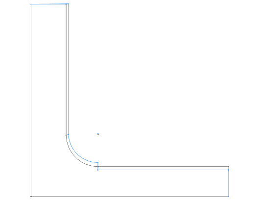
goes_bump_in_the_night_qlts4v.png


You can see there is a step near the root of the fillet. Likely, this was machined with two different tools or from two directions, so I understand HOW it happens. At prior jobs, quality would have rejected or reworked the part. At the current job, Quality says "because the step is within the surface profile tolerance, it meets print."

I originally thought block tolerance surface finish of 125 Ra should cover it. I then thought maybe we should say this is a controlled radius, but we see steps at the tangency point. The more I consider it, our surface finish should call out an Rmax that prevents this. I'm particularly concerned if this happens on aluminum parts prone to fatigue.

How do other people control for this type of manufacturing artifact with the print?
 
Replies continue below

Recommended for you

BiPolarMoment,
Imagine that each of the three features (the vertical surface, the radius, and the horizontal surface) were associated with a separate feature control frame of surface profile without datum references. Would you then say that the angular relationship between the vertical and horizontal surfaces is controlled by those profile tolerances? A general profile note without datum references would act the same. 

I sort of get why you are thinking that the tangency points (which are actually lines in 3D) could fall through the cracks, but I don't really consider it as a real issue, let me tell you why: The tangency line is only there in theory. On a real part, if it's made to print, the best you could have is some narrow border zone, not precisely defined in any way, where one surface blends into another. This zone can be considered as part of both surfaces, and points on this zone could be inspected as part of the control of one surface, or the other, or both. So if there is a step right between the radius and one of the planar surfaces on the part, it could be detected and treated as a violation of either the profile tolerance of the radius or the profile tolerance of the planar surface. 
 
Okay, this is a little bit of mixed message... the profiles are not connected, but the area in question has to be in one (or both) of them... sounds like they are defacto connected at that (each) junction? In any case the fact that it can be inspected as "one [...] the other, or both" still makes it ambiguous, no?
 
The main problem is that this would limit the overall form of the part to be within some tiny amount of the true shape. Which solves one problem by spending a large amount of money machining it to be nearly perfect and a larger amount in inspecting it and fitting all the data to see that it conforms. The more ideal goal is to allow the form to vary a lot (while remaining functional) but not to allow irregularities, like steps, which are features that don't appear on the drawing.

I might not care, for example, if a hand rail is 2.00 inches or 2.25 inches in diameter, but I do care if there is a sharp step that gouges my hand if I slide my hand along the hand rail. Sure, making the tolerance to be 0.001 inch will make the rail smooth, but at considerable expense for the overall dimensional control when all I really want is smooth transitions if the size/form varies.

Y14.5 doesn't deal with that requirement. I think it is because they don't see that as acceptable workmanship. The closest they come is profile tolerance zone transitions that say, effectively, a part with a smooth transition is acceptable, but it does not force the surface to have a smooth transition.
 
BipolarMoment,
This is a really minor issue. Yes, I could imagine a case where it could be ambiguous which feature is non-conforming if the violation is right on the border.
But there would be no way for the separate profile controls to affect the angular relationship allowance between the two planar features.
 
3DDave said:
The main problem is that this would limit the overall form of the part to be within some tiny amount of the true shape.

If you mean that the datumless general profile note would act similarly to profile all-over, then no, it would apply to features individually. The note would effectively control form, UOS. Cylindrical features can be excluded. If this is too costly or troublesome, the control could be applied directly in the drawing views only to some features that are at risk of stress concentration or where irregularities need to be tightly controlled from any other reason.

The handrail example could be solved by a cylindricity requirement. Plus, any sharp defects that may cut hands can be eliminated by an appropriate surface treatment.
 
Perhaps you've never used a hand rail, but they don't need to be perfectly straight and can be somewhat oval, but sure, using hydraulic shaft tolerances to steady me on the stairs would be fine and very expensive. I don't believe a 0.25 inch sharp shoulder bump can be taken up with a surface treatment.
 
3DDave,
You didn't comment on the first part, but I hope you now agree that a datumless general profile note would not "limit the overall form of the part to be within some tiny amount of the true shape".

As to the handrail example and similar cases - straightness, cylindricity, total runout, or profile applied on a cylindrical part would control bumps/steps, and other form errors. If this is not desired, and you are looking to limit only bumps/steps without limiting other form error types such as bend or ovality, there is no other choice but to have some document or notation defining what a bump/step is and specify a custom control to limit it.
 
The profile tolerance is the deviation from the nominal surface. If that number is small then the overall form must be within some small deviation from the true shape. Since it applies to the entire surface it is a simultaneous requirement for the entire surface.
 
3DDave,
Looks like you are using the term "surface" in the general sense, like the outside layer of an object.
In the tolerancing language terms (ASME Y14.5), the typical part has more than one surface. Each part feature is a surface or a collection of surfaces.
"A simultaneous requirement for the entire surface" - if that's one at a time - then yes. Also, not for all surfaces of the part, but for each surface to which the tolerance applies - those not otherwise specified, if the general tolerance note includes the UOS wording as it does typically.

There would be no simultaneous requirement or any sort of pattern that connects the tolerance zones, since the profile tolerance in the note would not include datum references to impose a simultaneous requirement (per section 4 of Y14.5-2009) and so none of the following would apply: "nX, n COAXIAL HOLES, ALL OVER, A ↔ B, n SURFACES, simultaneous requirements, or INDICATED" to create a pattern per the section 1 definition (note the plural in "SURFACES").

But if that's not clear enough from some reason, "INDIVIDUALLY" could be added for clarification, and the problem is solved.
 
I think you two are now finally arguing about where I was tripped up... my interpretation was that those three segments constitute a singular surface due to the illustrated tangency unless you intentionally segment it (e.g. A↔B, B↔C).
 
BiPolarMoment,
It is the opposite.
By default, a profile tolerance applies to a single surface/feature, unless you group several of them by A↔B, all-around, all-over, the number of places where the tolerance applies being specified in one way or another, indication of features as belonging to a group by a labeling letter, or if a simultaneous requirement is in force.
The argument with 3DDave is actually empty, as the standard is quite clear about it.
Hope this clarifies the matter, and you aren't tripped up anymore.
 
Can someone explain to me why adding a note of "Max Rz 125 microinches" doesn't cover this requirement? (In practice - if you want 125 microinches Ra then you should allow a bit more; 200 microinches(?) Rz.)

I get why Ra and RMS won't cover this issue. Those are varying methods of calculating an average. Rz is the maximum difference between a peak and trough. This specific issue is why Rz can be called out?
 
I think a Max Rz is perfectly correct solution. However, it will work best if the areas of concern can be directly measured with a profilometer. I think our profilometer probably can do it, which makes it appealing to me.

I think that's the element of many of these ideas that will separate really good solutions from the technically correct solutions. 1) will it be readily understood by a machinist with common working knowledge of GD&T (and not an advanced degree) and 2) can success be measured directly using common tools? Short of situations involving a Tier-1 supplier producing thousands of parts, I find these questions to drive most of how I tolerance and control a part design.
 
Burunduk - you would be less confused if you pointed to a use of profile without a datum feature reference. In any case in every other use of datumless references all the surfaces/features involved have a simultaneous requirement.

Perhaps you mean the standard is clear because it has an example of how you believe it is to be interpreted? The null feature reference is still a reference, just like is used elsewhere in the standard.

 
What's also bad about Burunduk parroting of some verbiage is that that interpretation (an incorrect one) just comes back to the original problem - allowing a discontinuity between adjacent portions of the part. Either argument produces a failure of the Burunduk suggestion - either very expensive or failure to fix the problem. Good job.
 
3DDave said:
you would be less confused if you pointed to a use of profile without a datum feature reference.

Had you read what I explained earlier, you would learn that profile without datum references controls only the form of the feature. See fig. 11-19 in ASME Y4.5-2018 to get yourself familiar with this tolerancing practice.

3DDave said:
In any case in every other use of datumless references all the surfaces/features involved have a simultaneous requirement.

If that was true, any time anyone would specify a datumless profile tolerance on basically dimensioned rounds or fillets connecting planar features at different locations on a part (which is a scheme chosen to avoid the more ambiguous directly toleranced radius dimensions), it would force the creation of a pattern of these rounds/fillets.

3DDave said:
The null feature reference is still a reference, just like is used elsewhere in the standard.

You would be more convincing if you pointed to that "elsewhere", specifically where the lack of datum references or, as you call it, the "null feature reference" is the sole grouping method to specify a pattern.

As for "allowing a discontinuity between adjacent portions of the part", this suggestion of yours is based on the poorly thought-through assumption that where there is a step produced between two tangent-designed features, it is legitimate and feasible to "chop" each of the two tolerance zones exactly where the step begins from each direction, to prevent each of the two profile controls from detecting that step. This is a faulty premise that was already covered in this discussion.
 
B said:
If that was true, any time anyone would specify a datumless profile tolerance on basically dimensioned rounds or fillets connecting planar features at different locations on a part (which is a scheme chosen to avoid the more ambiguous directly toleranced radius dimensions), it would force the creation of a pattern of these rounds/fillets.

Yes, it would. That's what the symbol/phrase "SEP REQT" is for if that's not what you want. OTOH, if you have used datum features and profile tolerances on the surfaces then any radii not sharing that datum reference frame don't need to even be on the part - quite the problem that you have created.

B said:
This is a faulty premise that was already covered in this discussion.

No. It wasn't. If there are two profile controls, the step is allowable as conformance to the zones is independent. There is no requirement to meet both zones at the same time nor to be continuous in curvature.

You know exactly what figures there is a tolerance controlling multiple features with no datum feature references. How can that be if datum features (plural) are required? That means at least two datum features are required to establish a Simultaneous Requirement. Perhaps the committee got that wrong and you alone have it right?
 
3DDave,
"SEPT REQT" is inappropriate with profile or position tolerances that don't include any datum references. Based on the definition of a simultaneous requirement, at least one datum reference has to be included in all tolerance specifications that invoke that requirement.

3DDave said:
You know exactly what figures there is a tolerance controlling multiple features with no datum feature references

No I don't.
I suggested you to provide evidence to support your "null feature reference is still a reference" theory, which you haven't done. I still encourage you to point to any text wording or even a single example figure in the standard where a pattern is created exclusively based on common lack of datum references, without any official (text supported) or even unofficial (such as the single FCF with multi-leader, no longer appearing in '18) pattern grouping techniques.

3DDave said:
There is no requirement to meet both zones at the same time nor to be continuous in curvature
And there need not be. As I explained, either of the tolerance zones for the two features nominally meeting at the common tangency can drive the rejection of an irregularity located wherever someone may assume that the tangency is supposed to be on a physical part.

3DDave said:
OTOH, if you have used datum features and profile tolerances on the surfaces then any radii not sharing that datum reference frame don't need to even be on the part - quite the problem that you have created.

Curious idea - nonexistent radii are conforming, and I'm the one who created that problem. Is that unique to radii, or can other types of features be missing from the part too? According to your logic, if one of the part features is out of tolerance, and it's not in a simultaneous requirement with anything else, I could rework the part and plainly cut that feature off solving the problem. Per the same logic, in some cases I may even be able to cut a part in half and hand over a half part to inspection, and it would be found conforming.
 
Sure you do. You scan every word and diagram looking for flaws and I know you have done so for this. You won't admit to this as it undercuts your argument. If I point it out you will claim it doesn't apply to this case, but if it supported your argument it would be there in your reply front and center.

Per the definition of simultaneous requirements in your understanding it requires at least two datum feature references. One is insufficient. You read that paragraph. It's plural. That's what you wrote was the case.

How are the radii non-existent? It's your example which you are now denying. Good job.
 
3DDave said:
Per the definition of simultaneous requirements in your understanding it requires at least two datum feature references.

This is not per my understanding, rather it is your misunderstanding.
If the same primary datum feature is referenced in several location-controlling tolerances, it is still a simultaneous requirement, regardless of the lack of any lower precedence datum references. It doesn't help you to be pedantic about the plural verbiage in the simultaneous requirement definition because your "null feature reference" is also singular. And it is definitely not an excuse to deny that explicit datum references are needed.
If the plural verbiage is a flaw, you are the one who made the effort to find it in order to base an argument on it, not me. I don't need to scan every word and figure in the Y14.5 standard to know what's in it, because I use it. Yes, I can bring a reference to the document to address a specific point if needed, and I appreciate when others do the same. Why would anyone choose to criticize this, is beyond me.

I suggested you get familiar with profile tolerances without a datum reference, have looked into it? Your learning process of this concept will not be complete until you realize that they only control the form of the feature, and not the mutual location and orientation between similarly toleranced features, unless the features are grouped to a pattern by one of the acceptable methods.

If you want to promote any other interpretation, it is up to you to present the back-up for it, rather than hiding it based on your predictions of my reactions.

3DDave said:
How are the radii non-existent? It's your example which you are now denying. Good job.

Well thank you, but it was your assertion that "any radii not sharing that datum reference frame don't need to even be on the part", not mine, I don't deserve the credit
 
Status
Not open for further replies.

Part and Inventory Search

Sponsor