Continue to Site

Eng-Tips is the largest engineering community on the Internet

Intelligent Work Forums for Engineering Professionals

  • Congratulations KootK on being selected by the Eng-Tips community for having the most helpful posts in the forums last week. Way to Go!

What type of Truss support connection should be considered in calculations?

Status
Not open for further replies.

bluestar9k

Structural
Nov 11, 2016
31
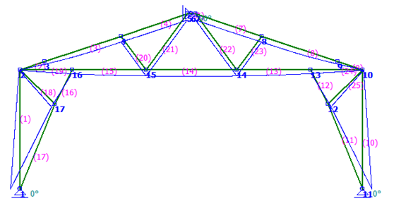
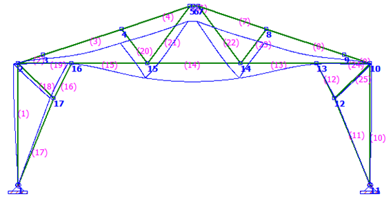
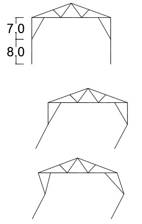
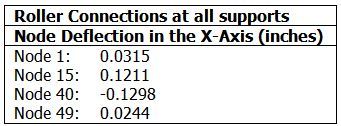
The truss shown below sets on top of a 2”x4”x8’ wall with studs 16” OC; so the bottom chord is around 15’ off the ground and the truss supports are 8’ off the ground. The truss shown is one of a series of trusses set on 24” centers. The bearing wall is freestanding for 14’. Thus there are 7 trusses exerting deflection or lateral force on the freestanding wall. At the ends of the freestanding wall are lateral wall set at 90 degrees which form part of the room. The calculated lateral loads are beyond the capacity of dual 2x4 cap plate and deflections seem excessive. Shown below are 3 examples using a different combination of support connections and the resulting deflection and lateral loads.

QUESTIONS:
1. What combination of support connections should be considered for a freestanding wall?
2. How can the high lateral loads or excessive deflections be addressed?

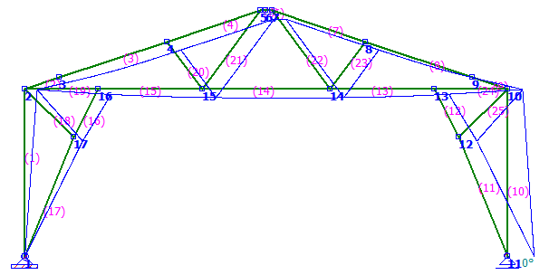
Table1_x14aka.png

Truss1_isdias.png


Table2_vxma2u.png

Truss2_kvglkt.png


Table3_jyzoly.png

Truss3_e6uyni.png


Note: I substituted a 6”x15# wide flange as a cap plate and a lateral loading of 340# on 24” centers exceeded the capacity of a 6”x15# wide flange. Max Unity Check = [highlight #FCE94F]3.6[/highlight].

Table4_dyccze.png

WF_Loads_haaozv.png

Plan View
WF_Deflection_tvommw.png

Plan View
 
Replies continue below

Recommended for you

1) The first two sketches are essentially the same solution.

2) I believe that the correct, and conventional modeling assumption for the design of the truss would be to represent it as pinned at one end and roller supported at the other.

3) Modeled as described above, the only place that you may see trouble with the top plate is close to the perpendicular walls at the ends of the run where the top plate may be restrained and, therefore, in a position to attract thrust. This is a common issue with scissor style trusses and, frankly, just never seems to actually cause any issues. My guess is that the roof and ceiling sheathing ends up keeping things in check rather well. A more sophisticated model that captured the interplay between top plate flexibility and truss flexibility would also probably yield more reasonable results.

4) Your first step towards stiffening this up probably ought to be running webs from 4-16 and 8-13.

5) Your lateral deflections are only about 1/4". I consider those numbers to not be too bad for such scenarios.

I like to debate structural engineering theory -- a lot. If I challenge you on something, know that I'm doing so because I respect your opinion enough to either change it or adopt it.
 
Additionally, anything that you can do to stiffen the upper truss should improve matters. Higher heel height, steeper pitch, larger members...

I like to debate structural engineering theory -- a lot. If I challenge you on something, know that I'm doing so because I respect your opinion enough to either change it or adopt it.
 
Hey KootK, good to hear from you again.

Everything sounds good except I need a little more clarification on deflections. You had mentioned the conventional model would be one pinned end and one roller and yes that is what I had learned also. However, the deflection with that scenario is not .25” as mentioned in your response (5) but rather .5” as noted in the 1st table. It would seem that .5” deflection would be a concern. In other words the wall would bow 1/2 inch in 14 feet. Concern? Yes/No?

Yep, the 2 trusses at the ends of the wall would pick-up the full lateral load as shown in 3rd table. I have not looked what it would take to reinforce the lateral walls but presently don’t think that will be an issue.

You know, the more I think about it now, the full deflection will occur in the center of the wall and the full loads will occur at the ends of the wall and there will be an incremental transition from the deflection to lateral load for those trusses which are placed incrementally closer to the ends of the wall. So lateral loading does appear to be a consideration, especially for those 2 and maybe 3 trusses closest to the ends of the wall.

I did run a case where I stripped out members 17 -16 & 11-12 and it produced a pure vertical load with minimal horizontal load (15Lbs). But, then I could not resolve in my mind if the horizontal load would reappear after those member were field attached. Any thought on this point?
 
Inner haunch should locate to a panel point.

Dik
 
The showed truss is supported by a wall, but is it a second floor? i mean is there a diaphragm?

if not, at least i'll consider the top chord of the wall as an spring to hold the rod support. For each truss get deflection of a unitary force placed at the truss location, while working with wood you'll get elastic behavior so this should be a valid approach. Set an element with the same stiffness as the deflection equation holding the rod and this element should be attached to a pinned support (your spring). To improve the spring stiffness repeat the above for each truss position and then sum the deflections that each truss generate on the other truss positions.

Depending on your top chor size the equivalent spring stiffness may be very small,especially if you take the chord's splices into account. But you'll get what you are looking for.
It would be easier if you model this in 3D.

If you have a diaphragm then take diaphragm's beams as the element that connect the pinned and roded supports.

If the beam members of the diaphragm are placed perpendicular to the truss plane then the connecting element will have a rigidity equivalent to the sheathing board stiffness, fasteners slip modulus and any other material in the force path connected in serie.
 
OP said:
However, the deflection with that scenario is not .25” as mentioned in your response (5) but rather .5” as noted in the 1st table.

That's why I mentioned that #1 and #2 are the same in practice. What you have is 0.5" separation across the truss. It's reasonable to assume that will manifest itself as 0.25" at each end. A tolerable value in my estimation.

OP said:
But, then I could not resolve in my mind if the horizontal load would reappear after those member were field attached. Any thought on this point?

The thrust loads would kick back in for any component of load incurred after the installation of the field attached members. That would include live, snow, and probably some components of the dead load.

I like to debate structural engineering theory -- a lot. If I challenge you on something, know that I'm doing so because I respect your opinion enough to either change it or adopt it.
 
Hey Koot,
On the second point, that was kind of the way I was leaning with respect to the diagonal members getting added to the truss in the field. Depending on when the member is added is an indication of the degree of lateral load it would transmit. If added right after the truss erection and before the sheathing/roofing then the lateral load would be computed from the full design load less the truss self-weight load.

On the first point, I guess we are thinking about two different situations, the model vs the field. In the model, if one side were pinned, as discussed, then the deflection would be .5” on the other end. However, from your comment, I gather the field deflections will act more like roller connections at both ends and thus .25” deflection on both ends.


Hey Ytyus
This is a single story structure and there is not a 2nd story diaphragm. You described an interesting approach and I shall have to give it some additional thought.
 
Thanks for sharing the approach view. But as i understood this, your structure is havely unstable.

Your supports doesn't really have much lateral rigidity. You'll get second order analysis implications. Such as P-Delta effect.
The third picture represent a higher mode of vibration.

def_diakez.jpg


If you want to model this take into account the wall stud, both pinned at bottom and the truss connected to the stud.
Your main lateral resistance will be given by the roof diaphragm supported by the lateral walls which will have their own deflections. Those are the support you need to represent.
 
how did you get the roller-roller model to run ? it should be unrestrained in X. or did you add an X constraint on the CL (say at the peak) ?

another day in paradise, or is paradise one day closer ?
 
he placed a pinned support at top side
 
that should be a clue that this is not a good model.

99% of us would I think model the supports as pinned/roller. A sensible question is "but both ends are built the same way. why are they different (in the model) ?" Well, you can make them the same, only not pinned/pinned (as this sets up an unreasonable reaction due to the immobile constraint point. The "best" model would have both ends supported by a finite stiffness, allowing a small displacement at both ends (as opposed to zero with both pinned). If there is no side load, the Fx should be small.

another day in paradise, or is paradise one day closer ?
 
Hey rb1957
By adding a roller at the apex of the truss, rotated by 90 degrees, I was able to run the case where all supports were set to roller. I used a roller because I didn’t want to restrict any vertical node deflection. I felt there would be negligible horizontal deflection at the crest of the truss.

Hey Ytyus
My apologies for not providing the whole picture. I wanted to provide only enough information to address the original question in order to curtail any side issues that may arise.

The truss shown is the center truss of the structure and there are mono (1/2 Howe type) trusses attached on either side of the center truss. This should address the lateral rigidity; however, I feel the point you make is applicable to the free standing wall portion of the structure. I had already considered diagonal horizontal bracing in the mono trusses to address the issue you present and the reason I was looking at the lateral loadings produced from fixed support connections was for sizing considerations.

Today I ran a full section case as shown below and the lateral deflections are minimal as shown in the table. (Yeah, yeah, I know, I still have more work to do to stiffen some sections; however, the maximum Y-Axis deflection of any node is 0.273 which meets the L/240 criteria for joists.) (Oh, you may notice the top cord of the center section is slightly higher than presented in 3 drawing of the original question. This was the original design and I dropped the top cord in an effort to improve stability and I have not made that change to the full section case yet. Nor have I added beams between nodes 27-38 & 31-35 as suggested by a few.)

Table-FullSection_sm4r7s.jpg

Full_SectionGeometery_mezcd7.png

Full_SectionDeflections_pmzb8d.png
 
bluestar9k said:
I had already considered diagonal horizontal bracing in the mono trusses to address the issue you present and the reason I was looking at the lateral loadings produced from fixed support connections was for sizing considerations

then place a unitary load on your diagonal bracing at truss supports, and draw an element with the equivalent stiffness in your model.
If several members share the same diagonals then an iteration is needed to accurate the results.

If you are holding the diagonal at walls make sure that joints are placed somewhere they can proportion orthogonal axis restraint, this points will be your pinned supports, it will be better if you represent the wall stiffness by other elements.
 
Hey rb1957
Good points made in your last post. Just to obtain a better understanding, why do you consider the pin-pin connection creates an unreasonable reaction? Are you assuming that in field applications there is support movement thus not producing true pin-pin reaction? In the case I ran, I did note the reactions were high but somewhat expected by restricting the lateral movement. Hummm, perhaps not in this case but I am sure there are plenty of cases where pin-pin connections are considered and used and that the Fx forces are addressed.

On the finite stiffness issue (which I think is a great point), would you consider the horizontal bending strength of the cap plate a good finite stiffness to apply?
 
Hey Ytyus
Excellent consideration. I had not thought that far ahead but your process is clear and quite reasonable and I will add it to the model when I get to the point of designing the bracing. Thanks for your insight.
 
@ bluestar,
Pinning both supports creates a displacement constraint between the unmoving supports and the small movement required by the structure, hence the very large load shown by the OP. These two forces oppose one another. I suppose you could use these forces as the most conservative reactions. Over constraining models (and particularly unknowningly and unintnentionally overconstraining) is a very common problem with FEA.
Pinning one support and using a roller at the other is a very simple way to remove this redundancy (and unreality). And you can see the small movement the truss wanted to do. This is, I believe, the solution 99% of us would use without too much thought (and IMHO quite reasonably). But in the light of the very simple question "but both ends are the same type of structure, why represent them differently in the model?" then the "best" model is to use finite stiffness at both ends.


another day in paradise, or is paradise one day closer ?
 
should node 6 and 23 be co-incident ? or are you allowing the chords to workin bending ?

you need a member 22-24, or something else, to stiffen the obvious elbow joint.

another day in paradise, or is paradise one day closer ?
 
Hey rb1957
Thanks for the insight. Much appreciated.
Unfortunately, nodes 6 and 23 are not co-incident.
I wish I could add member 22-24 but that is not possible because member 23-24 defines a part of the pan ceiling.
 
Try with 26-32 as 2 members, both running on each side of the frame, then enlarge 6-38 through 26-32 and join 27 with the "new" 38. 6-25 doesn't need to be vertically disposed, maybe could be spaced near 26, shear should be taken into account in a different manner as normally programs does.

Perhaps a double members also could be useful running from 1 to 6-7 as an splice. But isn't enough by its own.

 
Status
Not open for further replies.

Part and Inventory Search

Sponsor