Eng-Tips is the largest engineering community on the Internet

Intelligent Work Forums for Engineering Professionals

Where in ASME Y14.5 does it mention about using basic dim as gaging point?

Status
Not open for further replies.

rollingcloud

Aerospace
Aug 9, 2022
167
0
0
US
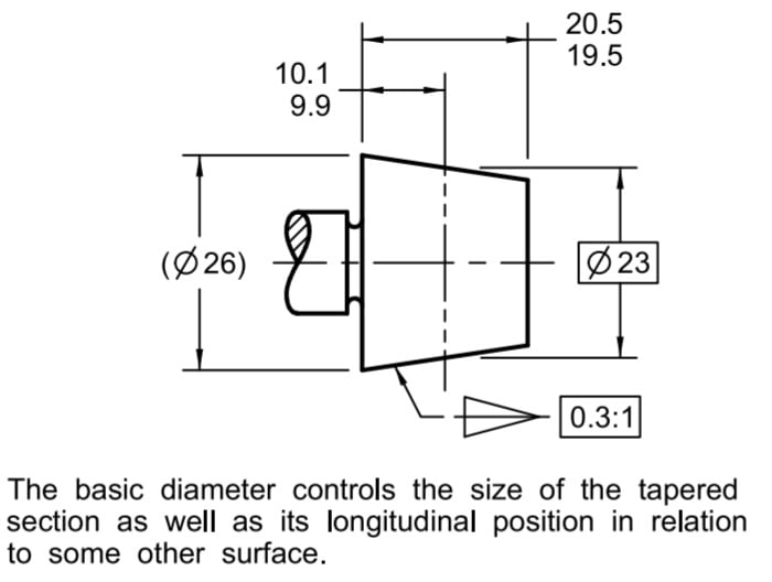
I have a drawing that does this:
Capture123_pr7awh.png

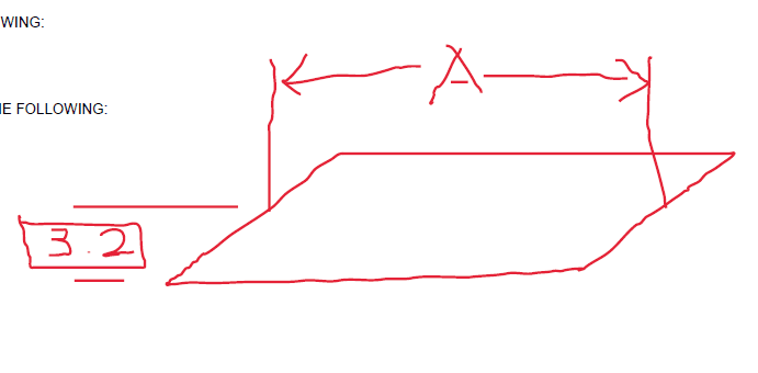
I know the standard allows the location of datum targets defined using basic dimension and letting the gaging tolerance act as basic dim's tolerance. But can this be extended to general dimensions?
 
Replies continue below

Recommended for you

It's not a Y14.5 kind of thing.
Closest thing you'll find in Y14.5 is for cones. Fig. 5-22 in the 2018 edition:

Screenshot_20240827_191102_Drive_icrokx.jpg


Locating a basically dimensioned diameter by a directly toleranced dim.
But that's not quite the same as what's in your drawing.

.
 
Hi, rollingcloud:

BASIC dimensions are theoretically exact (known as TED in ISO). You can indicate any dimensions as BASIC as long as they don't have tolerances. ASME Y14.5-2018 does not specifically emphasize it. Your BASIC dimension is OK as long as it points back to your coordinate system. You will have to make sure the feature that 3.2 BASIC dimension pointing to is long enough to qualify as dimension origin. Otherwise, you gage dimension "A" won't be repeatable.

Best regards,

Alex
 
rollingcloud,
You have not specified which version of Y14.5 you have in mind, so if, by any chance, it's the 2009, the figure you may want to look at is 8-18.

Notice that the "Means this" portion of the figure may be a little deceptive as the as-produced datum feature B is shown perfectly perpendicular to datum axis A, which allowed the committee to stay silent on the determination of the direction of the basic 18 dimension on real part - normal to datum plane B primary or normal to datum plane B secondary.
 
Since datum plane B in Figure 8-18 is defined as perpendicular to datum axis A per the datum reference frame, the measurement is both perpendicular to A and parallel to B. I believe this is covered under the Fundamental Rules as well as noting that the tolerance zone is defined in the [A|B] reference frame.

The standard committee absolutely should change the diagrams, in general, to be less "perfect" and more representative of cases that aren't so obviously right. The number where things just happen to work out and lack of those which represent less ideal conditions is a problem for those who expect picture examples to teach them.
 
There have been countless debates on the figure 8-18 and I am not sure another one is needed.

The whole reason I made that additional comment was to suggest that in the OP's case a similar dilemma might exist. In other words, there may be a need to clarify whether the "origin plane" of the basic 3.2 dimension is to be treated as primary or maybe it should be perpendicular to a primary plane established, for example, from the surface shown in the sketch.
 
The question is, does the basic dimension for a feature originate at the plane per the DRF or just not. I'd say the DRF.

There should be no dilemma, but there should be a lot of figures reworked to eliminate that potential mistake from entering the mental model in the first place.

The OP diagram is so ambiguous I can only guess what control is being attempted. I thought it was a flat view of a rhombus with both dimensions co-planer, such as for a gasket.

 
Status
Not open for further replies.
Back
Top