Verkstad
Mechanical
- May 17, 2011
- 44
Hi!
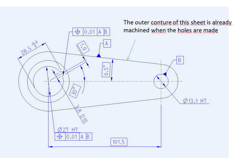
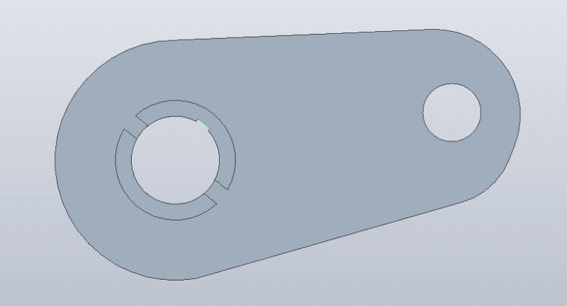
I need some good tips") . I don't know where i shall place the datum features in this drawing see picture below, since i dont have three surfaces normal to each other. I am using the iso standard.
. I don't know where i shall place the datum features in this drawing see picture below, since i dont have three surfaces normal to each other. I am using the iso standard.
I need to put a concentric tolerance between the holes. On the big hole i need to add a tolerance on the track inside the hole for a parallell key. And a toerance for the track that goes through the hole.
If there is anything i need to clarify just ask. It would been much easier if i could add a datum features on the center line, but the iso standard wont allow it.
I need some good tips
. I don't know where i shall place the datum features in this drawing see picture below, since i dont have three surfaces normal to each other. I am using the iso standard.I need to put a concentric tolerance between the holes. On the big hole i need to add a tolerance on the track inside the hole for a parallell key. And a toerance for the track that goes through the hole.
If there is anything i need to clarify just ask. It would been much easier if i could add a datum features on the center line, but the iso standard wont allow it.