Continue to Site

Eng-Tips is the largest engineering community on the Internet

Intelligent Work Forums for Engineering Professionals

  • Congratulations KootK on being selected by the Eng-Tips community for having the most helpful posts in the forums last week. Way to Go!

Which theory for an hand calculation

Status
Not open for further replies.

m.piron

Mechanical
Sep 20, 2019
16
Good morning, I need to made an hand calculation of this component:
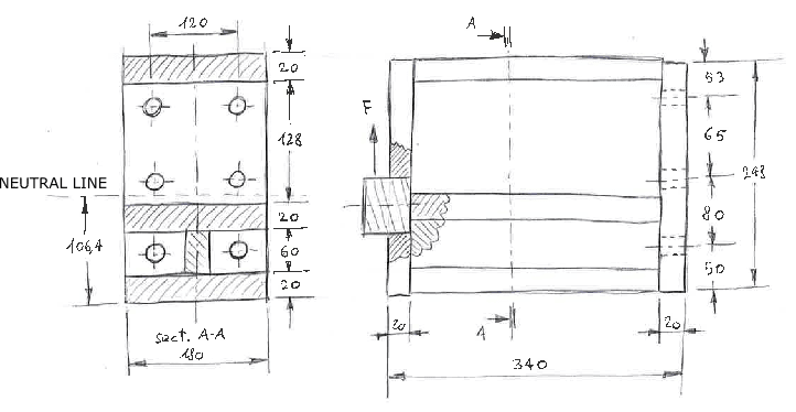
1577_001_wcsoxe.png


I verified it also with FEM, but I want to find the right theory to calculate it by hand.

1)I found the neutral line.
2)I calculate the stress on the lower and upper surface with the beam theory (but the L/H ratio is very low... can I do that?).
3)I calculate the reaction on the screws. In order to simplify the model, I removed the two central screws. The force acting on each of the 4 remaining screws is then F*340/290.

At this point, I can calculate the size of the screws needed to hold the force F.
But, how can I take into account this force on the stress of the structure?
The FEM results are very different from the calculation with beam theory, because the main stress is due to the axial force of the screws, not to the bending.
How can I take this stress into account? Membrane theory? Maybe not, the surface is too much small. Simple compression?

Thanks
 
Replies continue below

Recommended for you

What's your definition for the 'neutral line' for a start?

To simplify it, you have a plate at the top and an I-Section at the bottom sharing the load based on their relative stiffness. The two things don't work together as one 240mm deep beam, unless there's a Web you haven't drawn? So the neutral line is a bit of a mystery as to what it's signifying in that particular location.

Also where does the 290 come from, the overall depth is only 243? Leverarm to the top screws will be less than this obviously.

I feel like you've potentially misinterpreted how this thing is fundamentally resisting the load in coming up with your assessment methodology.
 
The two beams are connected together by two plate 248x180x20 mm at each side, you can see it in the right drawing. All the component are welded.
I consider the two beam as a single beam, and the neutral line is the line that don't change lenght with deformation of the beam... but maybe you're right, I must consider two separate beams with the total stiffness as a sum of the two stiffness.
The 290 come from the fact that I have 4 screws in total, 2 on top and 2 on bottom (I didn't consider the two on the center). So, I have 2 supports with a span of 145 mm, a distance from the load to the supports of 340 mm, the reaction of the supports will be F*340/145 in the lower and -F*340/145 in the upper. In each support there is 2 screws, so the force in the screw is F*340/145/2 = F*340/290.
 
plates are welded together ? (assume so, but not shown).

How did you calculate the "neutral line" (neutral axis to us) ? Is it the "neutral line" of the 6 fasteners ? (but I see you have neglected the inner pair)
Because it clearly isn't the neutral axis of the plates. Unless you've calculated effective width on the compression side ?

Your hand calc should follow the loadpath from the load to the reactions.
The load is applied to the spigot (produces shear and bending)
the spigot is welded (presumably) to the plate … these welds have to transfer the shear and bending moment.
now the load is in the LH plate, how do the supporting plates react it ?
I don't think the three (two?) plates will work together as a beam in bending, (there's no web joining them)
but rather the plates will act as individual cantilevers (each carrying a portion of the load, in shear and bending)
this then tells you the load carried by the welds (?) between the plates
then the RH plate takes these loads and reacts them with 4 (6?) fasteners
finally 4 (or 6) fasteners react these loads

another day in paradise, or is paradise one day closer ?
 
M.piron:
Your neutral line (our neutral axis), as it relates to beam theory, really doesn’t have much meaning on this weldment. Remember, we generally want a fairly long beam, (length to depth ratio) in the bending direction, bending length, since we want to be some distance away from large concentrated loads and the reaction points for the theory to really apply. The N.A. , by a slightly different meaning may still be o.k., in that some place in that region, the stresses change from a tension field to a compression field in the weldment, but it probably adds confusion to your thinking and problem description. I think looking at this as two or three cantilevers acting together, or better yet something of a rigid frame (small portal frame) resisting the load “F” and with fixed end moments at each welded end joint. The top flange pl. is just a single pl. fixed at its welded ends, depending upon the weld detailing. The bottom two flange pls. are actually a short WF beam with a web welded btwn. the two flgs., and then fixed at its welded ends. Except, that the WF shape is much stiffer than the top pl. canti. and much stiffer w.r.t. its end welds. This is approx. how your FEA software will see it, if it is modeled correctly.

I think I would change your detail a little, or at least look at a slightly different arrangement to see if it isn’t a little better. I would move the middle flg. up 40mm and extend the height of the web accordingly. Then, move the middle row of bolts down into this increased WF beam height. The vert. dimensions will now be 20, 88, 20, 100, 20mm, from the top. Now, the bot. two rows of bolts are in tension, with the tension magnitude being a function of the dist. from the top of the weldment. The top compression reaction area will actually be something akin to a triangular shape, with the compression resultant being down 1/3rd the height of your triangle assumption. Another reason for moving the middle flg. is to improve the welding access around those two lower flgs. When thinking about how this weldment (any structure) really acts, think about how it deforms and deflects, this will temper your assumptions about the design and analysis and help you understand the load paths and stresses, etc. With FEA, when done correctly, we can finesse the hell out of the stresses and deformations, but with reasonable, experienced, and conservative assumptions, hand calcs. will get you a good design too. Unless you are making hundreds of these weldments, you should understand how your weldment works and hand calcs. should probably be o.k. Then use the FEA to check your design and provide refinements.
 
Plane sections will not remain plane for this structure. This assumption is usually applicable for slender members. FEA only gives a reasonable load path but not necessarily the actual load path. You can analyze something like this to death and never get the actual load path. The welds and other manufacturing processes (residual stress from steel cooling after the rolling process) will generate all kinds of unpredictable residual stresses that FEA does not account for. In my experience, the best thing to do is assume a reasonable load path. You choose the load path. Make sure the load path is complete and all the required strength and buckling checks are made for that load path. Use good detailing and practices to ensure ductility.
 
I should also mention that you should be careful with prying action on the bolts. The tension load on the bolts can get amplified. Unless you are using FEA with non-linear and gap elements, this behaviour is very difficult to account for. However, in similar situations, I assume a reasonable lever for the bolts, load path and do the calculations by hand.

The characteristics of what you are attaching too can also change the results for and FEA.
 
I'd point out as well your assumption regarding leverarm for the screw design is incorrect. You're sort of looking at it as a tension/compression on the screw locations over the full height.

Due to the fact that you've got two elements sharing the bending this won't be quite correct.

Firstly, the compressive part of the couple would be carried in bearing through the end plate material to the underlying material of the support. Not necessarily aligning with a screw location.

Secondly, the bottom screw location might for example try carry the moment from the I-Section with a bearing force located at the top flange of the I-Section. The bottom bolt would carry the tension, this would mean it may simplify down to a 40mm lever arm. Resulting in possibility of considerably higher screw force.

Now its not as simple as that, because bending and stiffness in the end plate might result in a more complex load path.

To simplify things if it's possible to add some 'web' between the I-Section and the top horizontal plate then you have more chance of arguing that the entire depth works as one beam, with leverarm being closer to the overall depth from top of assembly to the bottom screw location. Middle and top screws take a linear distribution of force based on distance from bottom screw to centroid of compressive bearing force.
 
then, summarizing:
1) my assumption of "neutral line" was wrong, I must consider two separate beam.
2) I must follow the loadpath from load to reactions, and look each component how it react.

I try to repeat the hand calculation and the fem. I obtain results nearest to the fem if I think about it as a small portal (as suggested by dhengr).
Then, assuming the right plate (the one with holes) as a beam with applied the two moment, I obtain the stress results very similar to that obtained with fem (differences of about 30%).
 
In following the Neutral Axis location of his sketch, I would like to ask the following. I am working on connection spreadsheet for beams with added plates, stiffeners etc.

[ol 1]
[li]Is the neutral axis determined by doing the ΣYbar*Area/ΣArea where the tension zone is only bolt areas and the compression zone is only plates in compression (including web plates) and only bolts if they can take compression?[/li]
[li]Is the N.A. location independent of the moment, shear and axial loads?[/li]
[/ol]

These are my current concepts but I know some people use different methods.
 
but however the neutral line is determined it doesn't, IMO, affect the solution … the plates carry the shear and bending as separate plates (cantilevers).

another day in paradise, or is paradise one day closer ?
 
Status
Not open for further replies.

Part and Inventory Search

Sponsor