Eng-Tips is the largest engineering community on the Internet

Intelligent Work Forums for Engineering Professionals

  • Congratulations waross on being selected by the Tek-Tips community for having the most helpful posts in the forums last week. Way to Go!

Why Expressions with “p1; p2; p3;…”? 1

Status
Not open for further replies.

MFDO

Mechanical
Aug 10, 2005
217
0
0
CA
mf_exp_20161119_01_x7ac8x.jpg


Above is a component from PDW library. When defining expressions, is it necessary to say,
p1=A; p2=B; p3=C; ….
And then
A=X1; B=X2; C=X3; …. (Where X1, X2, X3, … are any corresponding values)

Why couldn’t it be as follows, directly specified by catalogue variable or a variable name?

mf_exp_20161119_02_lv2n31.jpg


Michael Fernando (CSWE)
Tool and Die Designer
Siemens NX V10.0 + PDW
SWX 2013 SP3.0 X64
PDMWorks 2013
Logopress3
FastForm Advance
FormatWorks
 
Replies continue below

Recommended for you

I see no reason to do it more complicated than necessary.
Might have been a person setting these parts up that did not see the simpler way of doing it.


Regards,
Tomas
 
I see this with almost every component done by many long-term NX users. What could have influenced this? Just negligence?
I’m wondering if it’s just a bad practice that could be avoided or if it’s necessary to have “P”s to avoid any issues or to make it easier later.


Michael Fernando (CSWE)
Tool and Die Designer
Siemens NX V10.0 + PDW
SWX 2013 SP3.0 X64
PDMWorks 2013
Logopress3
FastForm Advance
FormatWorks
 
I hope Taylor Anderson reads this and comments.

As i see CAD users, some will become power users and some will never.
they might both work equally hard but where one creates elegant models the other creates complex models with many many features.

I had one case a couple of years ago the shell of a mobile phone, where the user had extracted the original body three times and united to the original body.
The feature tree was more or less impossible to follow and understand. We more or less had to ignore the history and do local changes on top. the model went successfully into production.

Regards,
Tomas


Another area I see is, lots and lots of Datum Planes created with expressions in a huge list starting from p1=A; then A=?? defined method. Then sketch elements are constrained to the datums. Why not directly dimension sketches with W=??, L=??, pin_d=?? etc.?

mf_exp_20161124_01_cnow4i.jpg


What’s your take? What am I missing? Are sketch dimensions not stable as creating Datums?


Michael Fernando (CSWE)
Tool and Die Designer
Siemens NX V10.0 + PDW
SWX 2013 SP3.0 X64
PDMWorks 2013
Logopress3
FastForm Advance
FormatWorks
 
The resulting geometry can bee seen as not as stable if later operations directly reference them (faces, edges, vertexes) then i would prefer to reference datum planes, thought i would not use datum planes but datum csys.
 
What is your point?
You have
addendum circle: P1=120
dividing circle: P2=100
dedendum circle:p3=80

Isn’t it rather clear to have
Addendum_circle =120
Dividing_circle =100
Dedendum_circle =80

Why do you want to use P1, P2, P3….? Is it just because, it’s the default of NX?

Sorry, now I don’t have time to go through everything in your link. Please direct me if I’m missing something special.


Michael Fernando (CSWE)
Tool and Die Designer
Siemens NX V10.0 + PDW
SWX 2013 SP3.0 X64
PDMWorks 2013
Logopress3
FastForm Advance
FormatWorks
 
Regarding constraining sketch objects to datums instead of having sketch dimensions.
At one point in time ( many many years ago, late 90-ies beginning of 2000) The NX Sketch had the issue that a dimension between two sketch objects could flip the objects from + to - ( due to some other model change), the objects swapped place, the dimension value stayed, then the sketcher simply accepted the new flipped position as the correct position. but the geometry was invalid.
Then constraining to datums was a more stable method.
i would guess that is what you see here.

(difficult to explain in words, i can draw an example.)

Regards
Tomas
 
This is most likely an example of what's known as 'chirality' and is often seen when solving simultaneous equations, which is the underlying mechanism in so-called constraint solvers, hence the reason why this phenomenon is seen when updating a sketch. It's basically a situation were there are more than one 'valid' result. And yes, there are things that can be done to mitigate the effect but it's difficult to eliminate in 100% of the cases.

For more information on this effect, see the following item:


John R. Baker, P.E. (ret)
EX-Product 'Evangelist'
Irvine, CA
Siemens PLM:
UG/NX Museum:

The secret of life is not finding someone to live with
It's finding someone you can't live without
 
I understand what you are trying to explain. In other software I have encountered this situation specially when I edit features and sketches with parametric child offsets.

In NX, both Datum Planes, Sketches and almost every model construction are driven basically by Expressions in a transparent manner. If flipping happens, Expression vector would be the culprit. This would affect equally on both Datum Planes and Sketches. So I wonder if this flipping issue is still a possibility after many enhancements and fixes.

The way I understand, Sketches are fairly new to NX and most of the NX old-timers don’t use it to its potential. The other obvious question is, should we still continue with those old bullet-proofed bulky methods after years of R&D work?

Strangely Siemens guys are very silent or ignoring to comment. (I posted tis same question in NX Design Forum a week ago and didn’t get any comment)


Michael Fernando (CSWE)
Tool and Die Designer
Siemens NX V10.0 + PDW
SWX 2013 SP3.0 X64
PDMWorks 2013
Logopress3
FastForm Advance
FormatWorks
 
There has been a sketcher function in UG/NX since Unigraphics version 8.0, with the introduction of UG/Concept, in March 1981. Note that the current sketcher architecture was actually introduced with Unigraphics V13.0 in July of 1997. So the sketcher has been around much longer than what it would appear that you think it has.

John R. Baker, P.E. (ret)
EX-Product 'Evangelist'
Irvine, CA
Siemens PLM:
UG/NX Museum:

The secret of life is not finding someone to live with
It's finding someone you can't live without
 
John,
Basic curves are very popular choice than Sketches and most NX users/Cam programmes don’t know how to work with Sketches. They have some different ways of working than what is taught in NX training classes. Creating holes and Threads, Points, extrusions etc.

Anyway, getting back to the basic topic, Do you see any disadvantage in not creating expressions using P1=A; A=Value first and then defining P1 in sketch method vs. directly naming the sketch values?


Michael Fernando (CSWE)
Tool and Die Designer
Siemens NX V10.0 + PDW
SWX 2013 SP3.0 X64
PDMWorks 2013
Logopress3
FastForm Advance
FormatWorks
 
There is NO difference in the behavior of the sketch whether you enter the values directly into the Sketch expressions or you create a set of standalone expressions and then reference them from the sketch expressions.

John R. Baker, P.E. (ret)
EX-Product 'Evangelist'
Irvine, CA
Siemens PLM:
UG/NX Museum:

The secret of life is not finding someone to live with
It's finding someone you can't live without
 
Thanks John,
It confirmed that it is easily could start a design from a simply defined sketch. Sadly the PDW Reuse Library is also built with some outdated/unfamiliar features that is not easy to follow. Hope those developers will see some sunshine soon.

The next question would be, do you think that it's necessary to make driving planes to control sketches as limits? Is it a just a habit from the past or is there a still valid reason? Have you encountered undesired flipping happening lately in NX or has it identified and fixed?

Michael Fernando (CSWE)
Tool and Die Designer
Siemens NX V10.0 + PDW
SWX 2013 SP3.0 X64
PDMWorks 2013
Logopress3
FastForm Advance
FormatWorks
 
Michael, what would happened if there is more than just A=5, B=7 etc expressions? In some of mine designs I had over 500 parameters and I love that NX is naming them for me, so I do not have to think about what is next number to put in names. And for named parameters, just type A=5 in value field and filter equations with "Named" filter to see only those you made, that way you have directly named expressions.
"Basic curves are very popular choice than Sketches and most NX users/Cam programmes don’t know how to work with Sketches." This depend on where people had training, if they had it at all, how long they used other software that does not have sketches (I am curious what CAD software does not have sketch?), how good people are in adopting new behaviors that come with new software... and why nobody show them how good parametric design you can make with sketch, that is literally impossible without sketches.
If you like to use basic curves, do it, they exists and as you said some old timers who had problem adapting to sketches, still use it. I personally see basic curves as outdated and lot less useful than sketch functions, but I know that 3D sketch would be great upgrade to parametric design.
And why sketch is connected to plane... Can you tell me what software have sketch that is not connected to plane?

_____________________________
Enjoy your work and have fun!
 
MFDO --

Finally saw this thread, and since Toost asked for me to chime in... ;-)

There's no difference in the update behavior of the models in which expressions have been renamed, versus models in which the pXXX expressions reference user expressions. They both work identically, and there are pluses and minuses to each approach.

I don't have any first-hand knowledge of how the PDW parts you reference were created, but guessing based on what's there, I suspect that the basic parameters may have been prepared ahead of time and imported all at once, creating a bunch of consistent "User Expressions" up front to reference while modeling. This is a somewhat common technique when building a bunch of similar parts, or modular parts, when very consistent expression names are of primary importance.

Renaming the expressions directly certainly also works. The challenge is that these expressions are linked to the features that they drive, and that introduces some interesting behaviors when those features are deleted.

Generally speaking, when a feature is deleted, the expressions associated with that feature are cleaned up (deleted) as well, 
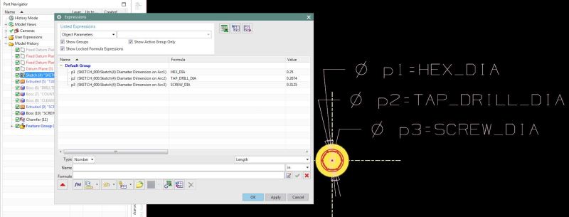
UNLESS those expressions are being referenced by other expressions, in which case the referenced expressions (only) are automatically preserved. But if, for instance, you had started a model with a nice sketch like this:

URL]


...and you'd gone to the trouble of naming all of the sketch expressions directly, as shown above, then you'd end up with a super-clean expressions list like this:

URL]


...and that looks awesome. For now.

Then, say you'd extruded that sketch, and in the process, had referenced the "height" expression in the End Distance expression (p6, here) of the Extrude feature:

URL]


Then you'd see that referencing relationship in the Expressions dialog like this, of course:

URL]


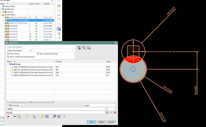
Now... Someday down the road, if you (or someone else) decides to create a different sketch here, like so:

URL]


...and reparent the Extrude feature to reference the second sketch, like this:

URL]


...and then delete the first sketch, then despite the fact that the Extrude is no longer referencing the first sketch, you'll actually still get the usual warning message about downstream effects:

URL]


...because that "height" expression (which is closely associated with the first sketch because the original sketch expression was renamed directly) is still being referenced by the Extrude feature. When you go ahead and choose OK here, the first sketch is deleted, along with ALMOST all of its expressions -- except "height", which was still being referenced by the Extrude. This leaves the Expressions list like this:

URL]


Now, there are a couple of choices lurking in here, as you probably see now:

[ul]
[li]We think it's good to clean up feature expressions when we delete features. (So we generally do.)[/li]
[li]But we also think it's important to preserve that referenced expression. (So we have, obviously.)[/li]
[li]Those other named expressions may or may not still be relevant, but we don't know. (You've gone to the trouble of renaming them, but at the same time, you've not gone to the trouble of actually referencing them anywhere yet. So [for 20 years or so] we've chosen to go ahead and clean them up for you.)[/li]
[/ul]

SO...

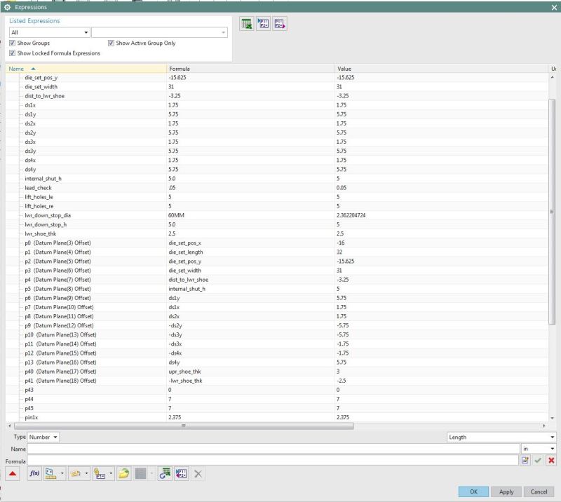
If those named expressions are important to you, it might make sense to create them as "user expressions" first (created directly, independent of any feature, either manually or by importing them) and then reference those user expressions. That way, they'll be sure to stick around until you manually delete them, and you won't find yourself trying to figure out which named expressions will be preserved and which will be deleted when a feature needs to go.

But you can choose how you want to work. :)

For what it's worth, we've taken this one step further in features other than sketches. While in most other feature dialogs, you can actually enter an expression name like this to create a new named expression:

URL]


And when you do that, we'll actually do this for you automatically:

URL]


For what it's worth. :)

Does that help a bit?


Taylor Anderson
NX Product Manager, Knowledge Reuse and NX Design
Product Engineering Software
Siemens Product Lifecycle Management Software Inc.
(Phoenix, Arizona)
 
Thanks Taylor for your input.

Glad that I asked! See, I learned that there is a reason for that madness.[thumbsup]


Michael Fernando (CSWE)
Tool and Die Designer
Siemens NX V10.0 + PDW
SWX 2013 SP3.0 X64
PDMWorks 2013
Logopress3
FastForm Advance
FormatWorks
 
Status
Not open for further replies.
Back
Top