Continue to Site

Eng-Tips is the largest engineering community on the Internet

Intelligent Work Forums for Engineering Professionals

  • Congratulations MintJulep on being selected by the Eng-Tips community for having the most helpful posts in the forums last week. Way to Go!

Why Expressions with “p1; p2; p3;…”? 1

Status
Not open for further replies.

MFDO

Mechanical
Aug 10, 2005
217
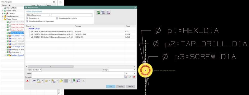
mf_exp_20161119_01_x7ac8x.jpg


Above is a component from PDW library. When defining expressions, is it necessary to say,
p1=A; p2=B; p3=C; ….
And then
A=X1; B=X2; C=X3; …. (Where X1, X2, X3, … are any corresponding values)

Why couldn’t it be as follows, directly specified by catalogue variable or a variable name?
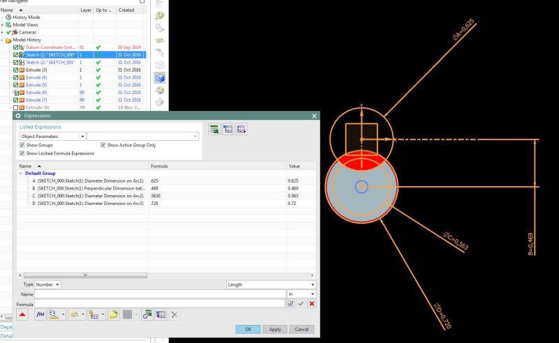
mf_exp_20161119_02_lv2n31.jpg


Michael Fernando (CSWE)
Tool and Die Designer
Siemens NX V10.0 + PDW
SWX 2013 SP3.0 X64
PDMWorks 2013
Logopress3
FastForm Advance
FormatWorks
 
Replies continue below

Recommended for you

Hi Taylor,
Is it necessary to constrain sketch elements to datum planes?

Michael Fernando (CSWE)
Tool and Die Designer
Siemens NX V10.0 + PDW
SWX 2013 SP3.0 X64
PDMWorks 2013
Logopress3
FastForm Advance
FormatWorks
 
MFDO --

Not necessarily, though it's certainly the most common approach.

If you were really trying to avoid datums, you could build a sketch attached directly to the face of a solid, for instance, and constrain that sketch to the edges of that same face or other objects in the model.

But datums are very common, datums provide a layer of indirection that is often useful (they can be reattached to a new parent in many cases, or offset independent of the underlying solid), and datum axes are a nice, consistent anchor for directions, in particular.

And so, as usual in NX, there are several ways to skin the proverbial cat.

Does that help?

Taylor Anderson
NX Product Manager, Knowledge Reuse and NX Design
Product Engineering Software
Siemens Product Lifecycle Management Software Inc.
(Phoenix, Arizona)
 
Thanks Taylor,
To be clear: (In case of a miscommunication)
Are you saying; If I’m to sketch a rectangle, it’s a good practice to have extra 4 boundary planes around where 4 sketch elements are constrained to.
Why isn’t it recommended if I directly dimension in the sketch? (Dimensionally constrained directly) Where could it fail?


Michael Fernando (CSWE)
Tool and Die Designer
Siemens NX V10.0 + PDW
SWX 2013 SP3.0 X64
PDMWorks 2013
Logopress3
FastForm Advance
FormatWorks
 
Ah, I see what you're asking.

No, that's certainly not necessary. I thought you were asking more about the placement plane.

Generally speaking, dimensions within the sketch will be quite stable. If you get a skittish one that tries to flip (more common 10-15 years ago, but much more rare these days...) then a strategic datum plane or axis may help nail it down.

But as general practice, would I constrain *everything* to a datum plane? Oh, no. Heavens, no. :)

Taylor Anderson
NX Product Manager, Knowledge Reuse and NX Design
Product Engineering Software
Siemens Product Lifecycle Management Software Inc.
(Phoenix, Arizona)
 
Status
Not open for further replies.

Part and Inventory Search

Sponsor