Continue to Site

Eng-Tips is the largest engineering community on the Internet

Intelligent Work Forums for Engineering Professionals

  • Congratulations GregLocock on being selected by the Eng-Tips community for having the most helpful posts in the forums last week. Way to Go!

Why my close-loop CHW pipework has 87 psi close to the highest point? 3

Status
Not open for further replies.

Jeff1988

Industrial
May 7, 2020
30
Hello ladies & gents,

I'm tendering on a mechanical plumbing job for this building with the air-cooled chillers & all other equipment located on rooftop.

My client's engineer told me "the required test pressure on the roof will be approx. 925kPa". Considering we test 1.5 times of working pressure, the working pressure will be about 600kPa (87psi).

I wonder if 87 psi is a normal pressure for pump head + expansion pre-charge?

Not sure if this information is useful, but the farthest cooling coil is 130m away from the rooftop plant. (100m elevation & 30m horizontal pipe run)
 
Replies continue below

Recommended for you

QualityTime,moideen,LittleInch,

Yeah thank you very much. I'm digesting what you said. I think I understand most of your info, except what LittleInch means by "design for that as the pressure loss and then add up the flows from all the units".

I'll draw up something and try to clarify that. Thank you so much for shedding light on my questions!
 
What LittleInch is saying is:

[ol 1]
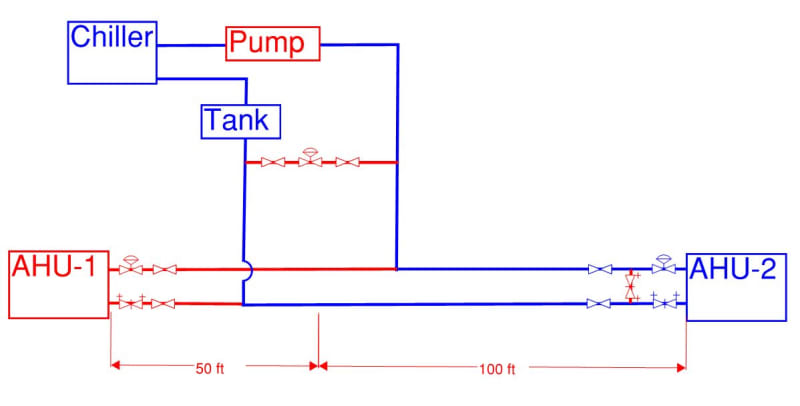
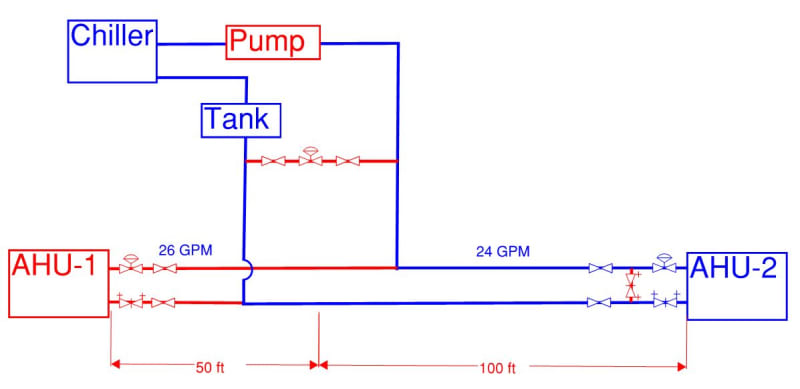
[li]figure out which one of your coils is the furthest away / highest frictional losses, design for that as the pressure loss. - As has been discussed the coil with the 100 ft run at 24 gpm gives you the highest friction loss in the example you have shown. This gives you a friction loss value which we will call "1"[/li]

[li]and then add up the flows from all the units - In your example you showed two cooling coil units. The total flow from both of the cooling coils is 50 gpm. 50 gpm is is running in the 2" 50 ft long supply and return lines from the TEE to the chiller. This gives you a friction loss value which we will call "2"[/li]

[/ol]
The total friction loss is = "1" + "2" + friction loss in the chiller + friction loss for supply and return piping back to the suction and discharge of the pumps + difference in velocity head between the pump suction nozzle size and the pump discharge nozzle size.

 
That is indeed what I was trying to say.

Your pump needs to be capable of pumping to the unit with the largest total pressure drop as well as supplying all the other units at the same time.

without flow control on the other units which essentially make their frictional losses the same as your worst case, the water flow will find the easiest way to get from high pressure to low pressure.
This is a very common problem in systems when commissioning them and solving balancing problems between multiple units.

Remember - More details = better answers
Also: If you get a response it's polite to respond to it.
 
Thank you QualityTime, LittleInch,

So when we calculate the total friction, we only need to consider the run with highest friction loss?
For example, to get the total friction loss of below, I only need to add up the friction loss in the blue path?

Capture_jej2ls.jpg
 
Please assume the flow rate has been balanced to be as below (just in case longer run doesn't make the bigger friction loss)

Capture_tfhtry.jpg
 
[ol 1]
[li]Yes[/li]
[li]The chiller is on the discharge side of the pump[/li]
[/ol]
 
QualityTime,

Thanks! I think I've got a rough idea how to estimate friction loss now.

You also mentioned "difference in velocity head between the pump suction nozzle size and the pump discharge nozzle size". I don't understand how pressure head transfer into velocity head.

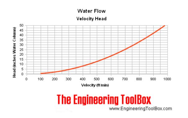
I've found some introduction on engineertoolbox.com and below graph. Just trying to figure out how it works.

Capture_pjbnma.jpg
 

The graph you provided above is not what i am talking about. Pumps, usually but not always, have suction nozzles one size bigger than the discharge nozzle. Because of this we have to do an additional headloss calculation

[ol 1]
[li]Velocity head is the pressure which is needed to increase the speed at which a liquid flows.[/li]
[li]Velocity head (ft) = ½(v2/2g) = ½(v)**2 /(2*32.2 ft/sec2)[/li]
[li]You know that water flow (Q) and convert it to ft3/s. You know the pipe diameter so therefore you know the cross sectional area (A)in ft2. Velocity (ft/s) = Q/A[/li]
[li]g = 32.2 ft/sec2 is the acceleration due to gravity and is a constant[/li]
[li]The appended table has the calculations done for you. They are close enough for what you are trying to do. In the example highlighted the we have a pump that has a 6" suction and a 4" discharge running at 400 gpm. The difference in velocity head (ft) = 1.27 (1.58 - 0.31)[/li]
[/ol]

The tables I previously uploaded has velocity already calculated for you. I will upload a sample table that has velocity and velocity head already calculated for you at a given flow at a given pipe diameter. I will also upload another handbook that has more complete tables to make things easy for you
 
 https://files.engineering.com/getfile.aspx?folder=68f53323-e8fe-4576-b2bf-c9fb3096602b&file=Hydraulic_Handbook.pdf
Thanks QualityTime,

If I have a close-loop system with X ft friction loss, and the pump has a 6" suction and a 4" discharge running at 400 gpm, which calculation is right?

1. Total Dynamic Head = X + 0.31 ft - 1.58 ft (my bet)
or
2. Total Dynamic Head = X + 1.58 ft - 0.31 ft
 
Thanks QualityTime,

I can't figure out. But velocity head difference is not huge compared to friction loss. I think as an amateur I'll just leave it out of consideration.

Yet another question... if we have a close-loop system served by a pump with 4" discharge running at 400 gpm (10.1 fps), can we possibly estimate the total friction loss?

I ask this because I can't see the connection between velocity and pressure.

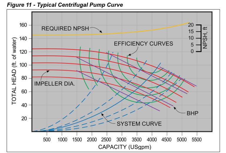
I've seen below graph before but it's complicated for me and I didn't dig into it. Is it relevant to above question?
Capture_r0jmfz.jpg
 
moideen,

Thank you for recommending mcquay software. I've downloaded their free Pipe Alator excel sheet. It's very handy.
And the sheet's got custom formula, which is a new useful trick for me.
 
[ol 1]
[li]I can't figure out. But velocity head difference is not huge compared to friction loss. I think as an amateur I'll just leave it out of consideration. - In high head applications, the velocity head is insignificant when selecting a pump. In low head applications, like yours, I expect the velocity head can be significant. I am not sure if the pump example that you have given is real life or something you dreamed up for talking purposes. If it is a real life example, I would have expected the discharge velocity on the pump would have been greater than 10.1 ft/s if the pump was properly selected. My advice to you is to do as I say and include the value in the calculations[/li]

[li]Yet another question... if we have a close-loop system served by a pump with 4" discharge running at 400 gpm (10.1 fps), can we possibly estimate the total friction loss? - The total friction loss is the blue line you showed in your sketch. The total dynamic head (ft) = total friction loss (ft) + difference in velocity head between the suction and discharge nozzle on the pump (ft). The units are all in ft. I am not sure what is the problem here. I would have thought you would have understood this concept by now[/li]

[li]I ask this because I can't see the connection between velocity and pressure. - Think of it this way, the more water you try to pump through a fixed pipe size the greater the water velocity and the greater the friction loss (i.e.pressure loss) per unit length of pipe. From a practical point of view how does one decide on the correct pipe size to begin with? For pump discharge piping the piping is sized for a water velocity of 4-10 ft/s and for the pump suction piping it is sized for a water velocity of 4-7 ft/s. I will guarantee you that if you have a velocity of, for example, 15 ft/s the piping will be screaming from the noise of the water flowing through it. Do not confuse high pump discharge nozzle flow velocities from discharge pipe velocities[/li]

[li]I've seen below graph before but it's complicated for me and I didn't dig into it. Is it relevant to above question? - Yes it is very relevant to a designer of this system. The blue lines represent the system head curve developed from (2) above at different flows. The reason why they have many blue curves is because your friction loss calculations will depend on what you initially assumed how smooth the inside of your piping is. If your piping is very new and has smooth inside walls there will be less friction loss and the blue curve you should be working with should be closer to one the lower sloped curves on the far right. If your piping is very old and tuberculated on the inside walls the friction loss will be higher and the blue curve be closer to one of the higher sloped curves on the far left. The 5 red parallel pump curves are for different diameter impellers. Without going in too deep, the blue system head curve is supposed to intersect the red pump curve at the sweet part of the curve at the condition point you have computed.[/li]
[/ol]
 
Thanks QualityTime,

1. Yes I should include it in calculations.

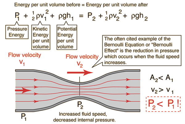
I got puzzled this morning because I was trying to fit velocity head into bernoulli principle, where the water already has a velocity/momentum. And I couldn't.
Bernoul_okdqtt.gif


Now I think velocity head is, when the pump starts up, what pushes static water to move and give it a velocity. If this idea is right, I can understand why "Total Dynamic Head = X + 1.58 ft - 0.31 ft".


2. I got the quesiton "if we have a close-loop system served by a pump with 4" discharge..." because I was trying to raise a reasonable figure for friction loss for the question "If I have a close-loop system with X ft friction loss, and the pump has a 6" suction and a 4" discharge running at 400 gpm, which calculation is right?".

If I say "I have a close-loop system with 10 ft friction loss, and the pump has a 4" discharge running at 400 gpm", I assume it will be unreasonable because a 400 gpm pump would have way higher head to cover 10 ft friction loss (given we only allow reasonable redundancy).
Sorry I asked the question wrong. I should ask about the relation between pump discharge volume (gpm) and pump Total Dynamic Head (ft). Now that I think about it, the pump curve graph I attached may be relevant.


3. I understand that (1) the higher the velocity, the higher the friction loss. (2) high water flow makes the pipe scream or cry. (3) in pipe size selection, we set a max velocity & max pressure drop as limitation.

But I don't understand the relation between GPM & Ft of head of the pump. Actually it's the same question in 2.


4. Ok then I'll dig into that graph. I used to spend a whole morning staring at it and figured out nothing. Hope I have better luck this time by reading your comments. Thanks.
 
Velocity head is not a consideration in pump head calculation, particularly in closed loop. Because it is a small digit. Here, 6-inch line connecting to 8 inch line as per the drawing. So again, the head loss comes down. To get a proper friction loss calculation, you have to calculate the pipe friction loss on each section of pipe where the size of pipe changing.
For instance, pipe length is approximate for example purpose:
36 l/s= 570 us gallon.
Start from pump discharge, 6 inch length of pipe= 20 ft, head loss at 570 gpm for 6 inch=2.5ft/100ft
Then head= 2.5*20/100=0.5 ft.,plus fitting loss like elbow, nrv, valve..etc.
Same like calculate each section of waste loop or critical length.
Next connecting to header 8 inch, so the head loss will come down 570 gpm for 8” =.55ft/100ft
Head= .55*200/100=1.1ft pluse line fitting loss. This way to be put in account until reach to the suction nozzle of primary pump.
If I am missing something, pointing it much appreciated
Thank you
 
Hi Moideen:

I would disagree vehemently with your approach on velocity head. Velocity head is part of the TDH calculations. It should never be ignored in the calculations no matter how insignificant you THINK the number is. You do not want to encourage bad engineering habits
 
hi, qualitytimes: Sir, I agree theoretically velocity head is a matter but in the practical calculation for a high head system it is insignificant. The hydraulic handbook, which you attached, page 10 says, it is insignificant because it is a comparatively small part of the total head. But, it is to be considered for small head calculations. take the subjected calculation, 6 in discharge, velocity 7ft/s then head 0.7ft. thank you
 
Hi

But I don't understand the relation between GPM & Ft of head of the pump. Actually it's the same question in 2.


[ol 1.]
[li]Ok. In order to select a pump the first step is to develop the system head curve. The example that you were providing is the first step in developing the system head curve. Look at the appended example. In this case the pump condition point is 50 gpm @ 12.94 ft. It is saying that you need a pump that can deliver 50 gpm against a resistance (total head i.e. friction loss) of 12.94 ft. It is one point on the curve but is the most critical point. You develop the rest of the curve by assuming different flows, 10 usgpm, 20 usgpm...etc to say 70 usgpm and working out the friction loss for each flow through the same piping.[/li]
[li]I am not sure if you know how to read a pump curve. Without going in too deep the pump performs only according to the curve. If your condition point does not fall (i.e. intersect) on the curve you have the wrong selection. Even when it falls on the pump curve it has to fall on the sweet spot of the curve. Operating a pump outside the sweet spot of the pump curve will cause a lot of problems[/li]
[/ol]
By developing the system head curve and plotting it on the pump curve, for an experienced engineer, it inherently tells you a lot of information. It is too deep to go into that now.


BTW having a computer program to calculate the friction losses is good but before you use the program you have to understand the fundamentals. Garbage in garbage out.
 
 https://files.engineering.com/getfile.aspx?folder=1a83da4c-65c3-470e-830c-559d853e00f3&file=Capture_a5eyg6.pdf
Hi Moideen, I am pretty sure this person only provided an example for simplified talking purposes. I doubt very much this is the real system. What this person is doing is a low head application. If you are familiar with the pumps that are suited for these type of systems you will know how important my comments are. What this is about is teaching the fundamentals. From experience an experienced designer can decide what to omit
 
Status
Not open for further replies.

Part and Inventory Search

Sponsor