Continue to Site

Eng-Tips is the largest engineering community on the Internet

Intelligent Work Forums for Engineering Professionals

  • Congratulations waross on being selected by the Eng-Tips community for having the most helpful posts in the forums last week. Way to Go!

Why my close-loop CHW pipework has 87 psi close to the highest point? 3

Status
Not open for further replies.

Jeff1988

Industrial
May 7, 2020
30
Hello ladies & gents,

I'm tendering on a mechanical plumbing job for this building with the air-cooled chillers & all other equipment located on rooftop.

My client's engineer told me "the required test pressure on the roof will be approx. 925kPa". Considering we test 1.5 times of working pressure, the working pressure will be about 600kPa (87psi).

I wonder if 87 psi is a normal pressure for pump head + expansion pre-charge?

Not sure if this information is useful, but the farthest cooling coil is 130m away from the rooftop plant. (100m elevation & 30m horizontal pipe run)
 
Replies continue below

Recommended for you

There is a possibility that the engineer made a boo boo. This happens more often than you think. Is this an experienced engineer or a young engineer? Nobody checks the design when it goes out the door anymore. I just commissioned a $30M Canadian sewage plant on behalf of the contractor. It took me 2.5 years!!! The engineer screwed everything up. And I mean everything. How do I know? Because they were trying to blame the contractor because EVERY piece of equipment was not working the way they thought it should. I have 38 years of experience in the design of water and sewage plants. I did my own calculations. Basically everything was over sized and did not have the turn down range for today's flow. The client has a big problem on his hands now.

By questioning things now, it will actually help the engineer. It gives him the opportunity to make things right. The alternative is ugly. The problem with a lot of engineering firms is that they cannot believe that they can screw things up.
 
QualityTime,

Yeah surely possible. This happens as often as I think, because I'm struggling with errors by the consultants in drawings & specs all the times. And I'm not sure how much pain my errors are causing downstream...

Thank you so much for sharing your knowledge and experience sir. Actually I started working as an estimator for HVAC plumbing 3 years ago, a little bit earlier than the time you started your currently finished project. Just within this relatively short period, I've seen a lot of projects (ours and other's) turning into a trouble, or what they call a "shit show"...

Hopefully I can reduce my parts in directing these kind of shows by learning more from you guys.
 
In my project, the engineer was getting the contractor to design the required changes (because they clearly did not know how to do it themselves). Because of that, the line between the role and responsibility of the engineer and the contractor was being blurred. I put a stop to that when I got on the job. Contractors specialize in constructing things and are not design engineers. The engineer IS to tell the contractor what to do.

The contractor was being blamed for a lot of things by the engineer and the client. The "damages" being assessed against them were very significant. Even the contractor thought his subs screwed up and he was beating up on them! It never occurred to the contractor that the engineer massively screwed up the project. Contractors are not elegant technical communicators and because of that they are at a disadvantage. The engineer always had the last word.

When i got on the job, I bent the bar, slowly but surely, 180 degrees to point directly at the engineer. One by one all the screw ups (structurally, mechanically, electrically, HVAC, SCADA, process etc) were proven to be not the fault of the contractor. The usual routine would be it would be blamed on the contractor. I would get involved and review what was designed and comment. I would hold meetings and telephone conference calls. The engineer would diddle for 2+ months and then the issue would be quietly dropped by the engineer. Needless to say, this has gone the legal route and it does not look good for the engineer or the client.
 
Talking about contractor doing the design, I've seen some cases where contractor took on the task because they know cost better. Sometimes their design may achieve some saving in construction cost (maybe not in running cost, I don't know).

One case was the consulting engineer got a design with water-cooled chiller in plantroom and cooling towers on roof a level above. The contractor submitted a confidential design with air-cooled chiller and won the job. After they won the job with their preliminary design & budget, they designed whatever they could to reduce cost, as long as their design meets the engineer's basic criteria.

It looks like a dilemma here. If an engineer not concerning cost does the design and contractor build it, the project may not be very cost effective. If a contractor takes on both design & construction, the client is like subjected to the contractor's mercy, and like you said are they really good at engineering?
 
EnergyProfessional,

Thanks for the info. That surely sounds a good point for me to start.
 
QualityTime,

By the way, this design is done by the contractor. So if it's really a boo boo, you've got another one in your example pool.
Although I reckon you don't need any more...
 
There is a reason why there are engineering firms and why there are separate construction contracting firms. As an owner, you get what you pay for at the end of the day. Choose your engineer and your contractor wisely
 
This appended example will help you out. The example shows a open system pump pumping from a lower reservoir to a higher reservoir. At a defined flow, the pump has to work against a calculated head. The Total Dynamic Head = (static lift) + (pipe friction loss) + (difference in velocity head between the pump suction and discharge nozzle size).

In a closed loop system, which it sounds like you have, the water is being recirculated in a closed loop. Once you manually fill the loop with water there is no static lift (i.e. you are not lifting water from a lower elevation to a higher elevation). Therefore Total Dynamic Head = (pipe friction loss) + (difference in velocity head between the pump suction and discharge nozzle size). What does this mean? It means from a pump point of view it does not matter if the cooling system is 10m high or 100m high.
 
QualityTime,

I'm still trying to digest the tech data you gave me. It surely is a lot of info for me to dig into... Thanks a lot.

 
QualityTime,

I'm just trying not to ask something stupid that already has its answer in the tech data.
 
QualityTime,

Thanks a lot. I'll study it after work.

Gosh, now I need a break from work to breathe.
 
Not as difficult as you think. Just draw a sketch of the system just like on page 9
 
QualityTime,

Yup now I got that static lift is 0 because it's a close loop system.

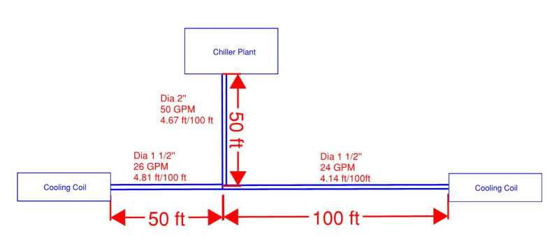
But I've got questions about how to calculate pipe friction loss of the whole system. In below sketch, which is the right way to calculate friction loss?
1. loss in Chiller plant + 50 ft/100 ft x 4.67 + loss at Tee + 100 ft/100 ft x 4.14 + loss in Cooling Coil
2. loss in Chiller plant + 50 ft/100 ft x 4.67 + loss at Tee + 100 ft/100 ft x 4.14 + loss in Cooling Coil + 50 ft/100 ft x 4.81 + loss in Cooling Coil

Capture_a5eyg6.jpg
 
Jeff1988 : you have to make an excel sheet in which arrange each section of pipe and calculate the friction loss. i have some excel file . i will post here after some suitable modification with your application. download mcquay software to know the pipe friction loss. it is free

thanks
moideen
 
Hi:

[ol 1]
[li]You have not drawn the entire system correctly. You should be showing the pumps.[/li]
[li]The diagram should be shown more like the first diagram that you posted AND you have to add the cooling coils.[/li]
[li]Correct me if I am wrong but the chiller plant should be supplying both cooling coils. I think that is what you mean but your sketch is inaccurate. A proper picture is worth a thousand words[/li]
[li]The friction loss is both on supply side of the piping and the return side of the piping (1. loss in Chiller plant + 50 ft/100 ft x 4.67 + loss at Tee + 100 ft/100 ft x 4.14 + loss in Cooling Coil + friction loss in return piping back to the common Tee + friction loss 50 gpm in 2" pipe back to the chiller)[/li]
[/ol]

You could have one thousand of the 100 foot cooling coil lengths running in parallel but you count the friction loss only once
 
The thing you need to work out is how the flow is being controlled to the 26 and 24 GPM you list.

Without some sort of flow control ( a valve of some sort usually) the system will balance out the different losses and your coil with the lowest total piping losses will flow more than one far away.

So the trick is to figure out which one of your coils is the furthest away / highest frictional losses, design for that as the pressure loss and then add up the flows from all the units. Then make sure that you can control the flow at the ones with the lowest frictional losses to prevent short circuiting

Remember - More details = better answers
Also: If you get a response it's polite to respond to it.
 
Hi,

What LittleInch is saying is that there is typically a motorized valve that controls the flow of chilled water into the cooling coil; otherwise you will have 24++ gpm going through the cooling coil flat out at all times and you will freeze everyone out in the room. I assume you have not shown this because you are just trying to get a simple answer to a simplified sketch without getting into too much detail. I would assume the actual design that you are working with has this control valve shown in the PFD.

There are many motorized control valve types that can be used to control the flow. They can be two way valves, 3 way diverting valves, 3 way blending valves,etc. Each of those types of valves has to be sized properly to be able to achieve linear control, with a good turn down, without hunting. There is a lot of engineering involved to get everything to work together as a system. The most important thing is turn down capability. I think that is outside of scope of what you are trying to do

Remember you are not trying to design the system. If you are not an expert stay away from it. Keep the lines of responsibility separate and clear. Have you approached the designer?

 
Status
Not open for further replies.

Part and Inventory Search

Sponsor