Eng-Tips is the largest engineering community on the Internet

Intelligent Work Forums for Engineering Professionals

Why we need 2 Callout's for a FOS? 2

Status
Not open for further replies.

ASHWA

Automotive
Oct 7, 2020
52
0
0
IN
Hai All,
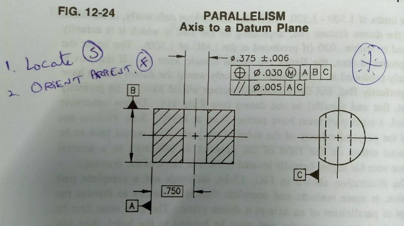
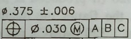
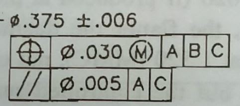
In the drg, the Hole is Located using Position Tolerance 0.010 at MMC, which is stationary.
Next, the Hole Axis will have to Orient and Float at 0.002 but within 0.010 at MMC.

My Question is, Why we need a Parallelism tolerance here & any purpose?

If the Hole Axis will have to Orient and Float at 0.002 but within 0.010 at MMC. How they will Measure the Axis of hole is within 0.002?

Kindly resolve Please.

 
 https://files.engineering.com/getfile.aspx?folder=ef3f2bc1-9884-481c-a0ce-ad387bd5011e&file=IMG_20201021_163304.jpg
Replies continue below

Recommended for you

Belanger said:
Are you thinking that it can't twist in that manner? Or are you concerned about datum A appearing in both FCFs?

I am thinking that one (smaller angularity in blue) is overriding the other(bigger angularity in black).
How you can take full advantage of the higher angularity tolerance if the smaller angularity tolerance is already in place?
 
3DDave said:
Because the larger one controls parallelism to the second datum feature simulator and the second one does not.

Yes, I do understand that, but my main questions about the physical realities of such callout remains largely unanswered.

Again, the questions are copied below:
"I am thinking that one (smaller angularity in blue) is overriding the other(bigger angularity in black).
How you can take full advantage of the higher angularity tolerance if the smaller angularity tolerance is already in place?"
 
greenimi,
Imagine the considered surface from your posted figure produced as flat as possible, at "exactly" 90° relative to datum A, and at 2° degrees relative to datum B. This one would utilize about zero of the 0.05 tolerance zone of angularity relative to A, but (depending on how large that surface is) the 2° slant could possibly use the entire 0.12 tolerance zone of angularity relative to the DRF established from |A|B|. It could as well deviate outside of the 0.12 tolerance zone and the part could be rejected.
 
Burunduk said:
Imagine the considered surface from your posted figure produced as flat as possible, at "exactly" 90° relative to datum A, and at 2° degrees relative to datum B. This one would utilize about zero of the 0.05 tolerance zone of angularity relative to A, but (depending on how large that surface is) the 2° slant could possibly use the entire 0.12 tolerance zone of angularity relative to the DRF established from |A|B|. It could as well deviate outside of the 0.12 tolerance zone and the part could be rejected.

3DDave said:
Draw the top view. You'll see a wider zone controlled by the first FCF than is controlled by the second one.

Thank you. Let me digest that. Appreciate your help
 
Hai All,
I also have the doubt from greenimi,

As from drg, 1. Angularity with [A] & 2. Perpendicularity [A]B] using the surface here is 90deg.

aa_lnliji.jpg


What can be the designer intend, to keep 2 Callout for a single surface?

Can be 1. for a operation & 2. for next operation ?

Any wrong in Question, pl. dont mistake.

Thanks.
 
There are other techniques to get reproducible results without using a reference to datum feature B.

Example - place parallels against the table and the angle block. Put datum feature A against the angle block. Put the controlled feature against the parallels. Turn the part to minimize the gap with the parallels and then clamp in place. Remove parallels. Use height gauge to check perpendicularity zone. Done.
 
Anbu Saravanan,
The reason that a designer may want to specify both callouts is that they don't mean the same thing, and both needed. Angularity to A controls only orientation to datum A. There is no datum B for this control and the orientation to datum feature B as far as this control is concerned can be anything. Even 45°, despite being shown parallel on the drawing. The perpendicular orientation to A must be held within 0.05.

On the other hand perpendicularity or angularity with reference to |A|B| controls orientation to both datums. Because datum feature A is referenced as primary it has a closer relationship with the true geometric counterpart that establishes datum A, than the relationship between datum feature B and its true geometric counterpart; datum feature A contacts the true geometric counterpart ar at least 3 points of contact while datum feature B may contact its true geometric counterpart at only 2 points. However, both the perpendicular orientation to datum A and the parallel orientation relative to datum B have to be held simultaneously within 0.12 when the requirement is evaluated.
 
To riff on Burunduk's recent comment -- think of the 0.12 this way: The designer wants to control angularity to datum B (within a more generous 0.12), while being mindful that the datum which the 0.12 is really measuring from (datum B) won't be fully flush with datum feature B, but may only touch 2 points.

John-Paul Belanger
Certified Sr. GD&T Professional
Geometric Learning Systems
 
Or - just what I wrote before:

It is useful in the event that the design is more tolerant of variation in what is essentially a parallelism to the secondary datum simulator in the first callout than variation in the perpendicularity to the primary datum feature in the second.
 
Dear Belanger,
For some weeks ago in this ex,
2_lvfxqg.jpg


I have a doubt, you said the independent pin that varies from 0.369 to 0.381, is that correct or will be from 0.374 (0.369 + 0.005) to 0.386 (0.381 + 0.005).

With Regards,

N.Anbu Saravanan.
 
The .369 to .381 is correct because the pin in question is just simulating the actual hole, even if it's tilted. The GD&T number is not factored into that.
However, if the parallelism callout contained the MMC modifier, then we could speak of a gage pin that is designed to include the .005. That would be what's called a "virtual condition" pin, which would be exactly parallel to datum A.

So again, because this parallelism does not have MMC, we stick with the expanding pin of .369 to .381, which would then itself be assessed for any parallelism error.

John-Paul Belanger
Certified Sr. GD&T Professional
Geometric Learning Systems
 
ANBU SARAVANAN, in case you wish to clear your doubt further by looking it up in the standard, the pin expanding from .369 to .381 described by Belanger simulates what is referred to as the Unrelated Actual Mating Envelope, and the axis of this envelope is considered as the axis of the cylindrical feature of size for orientation or position control.
 
Thanks Belanger & Burunduk,

Still a small doubt,

2_gmmuml.jpg


if we take the 1st segment of callout,
aaa_wefb0v.jpg


Hole at MMC,
0.369 + 0.030 (Bonus Tolerance) = 0.399
0.370 + 0.031 (Bonus Tolerance) = 0.401
" "
0.381 + 0.042 (Bonus Tolerance) = 0.423.

V.C = 0.369 - 0.030 = 0.339

I want to know that, now the Hole is just positioned or Manufactured?

If manufactured how the Parallelism refinement will take effect?

bbb_ete3ey.jpg


Since the 2nd segment is RFS, we check the Hole by using expanding pin of 0.369 to 0.381,

Just want to know in Manufacturing aspect of thinking.

Could be useful if we could know step by step process in a Hole making process using the above callout.

Thanks all.
 
I want to know that, now the Hole is just positioned or Manufactured?

I'm not quite sure of the distinction you're implying between "positioned" and "manufactured", but the specification on the product drawing is for the finished part unless otherwise noted (ie: a note specifying BEFORE PLATING, etc..).*

Could be useful if we could know step by step process in a Hole making process using the above callout.

Drawing specifications, unless specifically noted, do not dictate manufacturing process requirements or limits*. Its typically bad practice to do so especially if the one producing the part is different than the one designing it as it could place undue restrictions on manufacturing which could drive cost up or create issues which the designer did not intend. Its typically up to the supplier to determine the manufacturing processes that will meet the drawing specifications set forth by the designer and meet the specifications reliably with minimal scrap/rework to drive down costs and reduce potential quality leaks/issues to the customer.

Just take a look and fundamental rules 4.1 (e) and (q) from Y14.5-2018 for the ASME views on this.

ASME Y14.5-2018 para 4.1 said:
(e) The drawing should define a part without specifying
manufacturing methods. Thus, only the diameter of a hole
is given without indicating whether it is to be drilled,
reamed, punched, or made by another operation.
However, in those instances where manufacturing,
processing, quality assurance, or environmental information
is essential to the definition of engineering requirements,
the information shall be specified on the drawing or
in a document referenced on the drawing.
[...]
(q) UOS by a drawing/model note or reference to a
separate document, the as-designed dimension value
does not establish a functional or manufacturing target.

*There are less common in-process drawings but these are for manufacturing only and do not change acceptance requirements/specifications on the finished part.
 
Dear chez311 (Automotive),
Yes, Thanks for your reply.

Since i'm a student in GD&T, visualizing the process - makes the work more easier to understand.

The Designer design's a product drg, which has to go to shopfloor and is to be machined for the final product.

My intension is to know, how a designer thinks using these callout.

Since the drg. uses 2 - segment Position & Orientation callout, got this doubt.

Thanks for your (STANDARD) REPLY,

N.Anbu Saravanan.
 
Status
Not open for further replies.
Back
Top