Continue to Site

Eng-Tips is the largest engineering community on the Internet

Intelligent Work Forums for Engineering Professionals

  • Congratulations IDS on being selected by the Eng-Tips community for having the most helpful posts in the forums last week. Way to Go!

Why we need 2 Callout's for a FOS? 2

Status
Not open for further replies.

ASHWA

Automotive
Oct 7, 2020
53
Hai All,
In the drg, the Hole is Located using Position Tolerance 0.010 at MMC, which is stationary.
Next, the Hole Axis will have to Orient and Float at 0.002 but within 0.010 at MMC.

My Question is, Why we need a Parallelism tolerance here & any purpose?

If the Hole Axis will have to Orient and Float at 0.002 but within 0.010 at MMC. How they will Measure the Axis of hole is within 0.002?

Kindly resolve Please.

 
 https://files.engineering.com/getfile.aspx?folder=ef3f2bc1-9884-481c-a0ce-ad387bd5011e&file=IMG_20201021_163304.jpg
Replies continue below

Recommended for you

As you mentioned, the hole is located by the position tolerance relative to datum A. If that were the only callout, then position would naturally hold the orientation (parallelism) from datum A to the same tolerance amount. But the designer wants the orientation aspect to be tighter than .010 at MMC. So think of the parallelism callout as a refinement of position.
As for measurement, there are several ways. Physically, a functional gage could be used to check the parallelism: That would be a pin of Ø.496 mounted exactly parallel to another pin; the pin to simulate datum A would not have a fixed diameter but rather an expanding size, in order to lock onto datum feature A regardless of its material boundary.
An alternate way to measure the parallelism would be to use a CMM, which would probe each hole and mathematically determine the parallelism error.

John-Paul Belanger
Certified Sr. GD&T Professional
Geometric Learning Systems
 
Superb, Clear cut explanation.

Thanks Belanger.
 
Dear Belanger,
For functional gage to check parallelism, the pin dia would be Ø.496.

Is this By VCB,
IFOS (Hole) at MMC = MMC DIA - POSITION TOLERANCE

= 0.498 - 0.002

= 0.496. is this correct?
 
Yes, that's right. The pin I mentioned would be the "virtual condition" derived from the parallelism tolerance. That comes from .500 - .002 - .002.

I should also have mentioned that the physical gage for parallelism would have the two pins connected by a sliding distance. That differs from a physical gage for the position callout, which would have two pins at a fixed distance from each other.

John-Paul Belanger
Certified Sr. GD&T Professional
Geometric Learning Systems
 
Dear Belanger,
yes. Thanks a lot for the clarification.

I have a another doubt, in the attached file.

In this, Hole is 1. Located & 2. Oriented.

for Parallelism here the tolerance of Ø0.005 should float at Ø0.030.

To check the Hole, here we dont use Material condition in Orientation tolerance.

so, RFS is taken. and the Hole to check will be,

Ø0.381 + 0.005 = Ø0.386.

Iam i correct?

 
 https://files.engineering.com/getfile.aspx?folder=75c88a7b-ed3a-4d0a-911a-b6ee1f913c48&file=IMG_20201021_201916.jpg
I would slightly disagree with one thing you wrote... in that drawing the parallelism tolerance of .005 doesn't really float within the position tolerance of .030 because they have slightly different datum references. The parallelism callout references datums A and C, which creates a different reference frame (since datum C is secondary, rather than tertiary).

For your other question... it's true that the parallelism tolerance does not have a modifier, so it's RFS. Thus, there is no single number that simulates the worst case. You'd have to use an expanding pin to lock onto that hole, regardless of feature size. If there were an "M" after the .005, then we could arrive at a single number (virtual condition), but that single number would be subtracted from the hole's small size (your calculation is adding onto the hole's large size).

John-Paul Belanger
Certified Sr. GD&T Professional
Geometric Learning Systems
 
Thanks Belanger,
Ok, If it doesn't float, is it proper to say it will move within Position Tolerance zone?

Expanding pin to lock onto that hole of what dimension?

Thanks in advance.
 
It has no connection to the position tolerance other than sharing a common primary datum. So no, it doesn't move within.

The expanding pin for this parallelism would not be part of a functional gage. It would be an independent pin that varies from .369 to .381 (to accommodate the hole's size) and then this pin (or theoretically, its axis) would be checked for parallelism with respect to datums A and C.

John-Paul Belanger
Certified Sr. GD&T Professional
Geometric Learning Systems
 
ANBU, It is also useful to remember that datum references of orientation controls do not constrain translational degrees of freedom, just rotational ones, so the orientation tolerance zone is not limited in any way to reside within the confines of the position tolerance zone, fully or partially. Rather it is more correct to say that they are part of two independent requirements that should both be met. And as noted, the two tolerance zones are also established relative to different datum reference frames (sets of 3 planes normal to each other), in practice not likely to be coincident with each other. Consider that in the datum reference frame established by the |A|B|C| set of datum references, datum plane C could be simulated by contacting just one point on the surface of datum feature C (datum feature simulator B could prevent the part from making contact at two points on datum feature C). In the DRF established by |A|C| datum C is only allowed to be simulated by contacting two points. So these two datum reference frames end up being different and as I mentioned they work differently in terms of having degrees of freedom constrained relative to them. As a result, we cannot analyze the two tolerance zones as if one floats inside the other.
 
Thanks Belanger, for the detailed and clear explanation.
 
Thanks Burunduk, for the effort to clear the doubt. Now its cleared.
 
J-P, Burunduk and all,

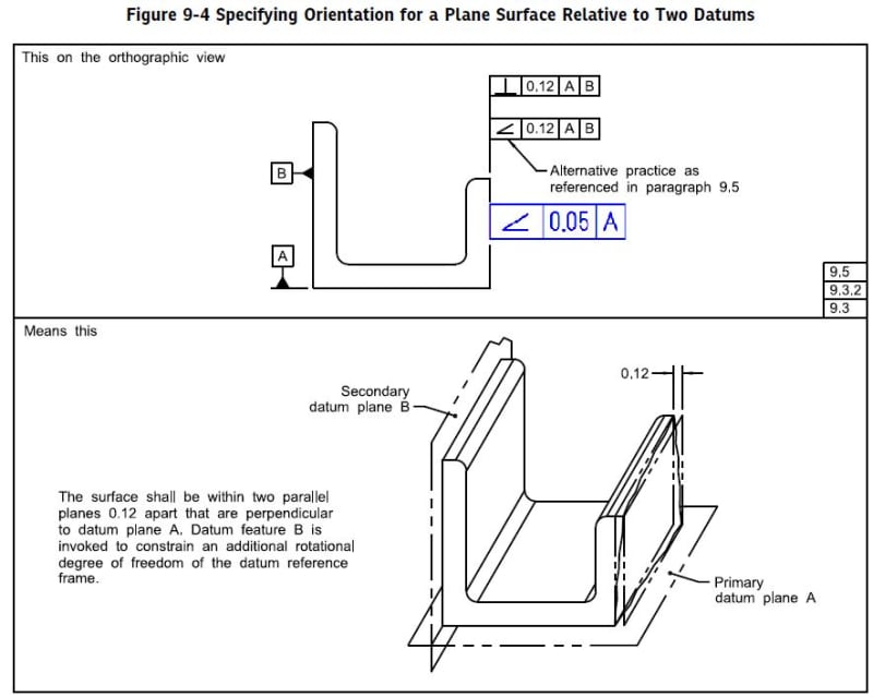
By the same token, I had a discussion with one of my GD&T fellow and there is still some level of confusion regarding those orientation controls (parallelism, angularity, perpendicularity) and to be more specific on why if perpendicularity is added to the right hand surface (as shown below in blue) than this new addition does not nullify the first anularity (or perpendicularity). Still have hard time seeing how both angularities (or perpendicularities) can be meet simultaneously and one being refinament of the other.

And yes, I do know that black angularity has datum feature B secondary and blue angularity does not have it ( and has only datum feature A primary), but still we cannot see how if blue is within 0.05 then why black is not redundant.

There are some people claiming that if the blue calout is added then the black callout is useless.

I talk with other GD&T experts on a different platform and I am still stuguling finding a clear explanation. maybe a picture with "as made" surface would help.

Any opinions? Any thoughts?

P.S. If needed I will open a new thread.


Q_t8tvai.jpg
 
Welcome to set theory - the various requirements are individual sets; a compliant part is one that exists at the intersection of those sets. The usual whining about "double dimensioning" should only be a caution against creating a situation where there is no intersection possible, but is usually complaints because someone told them never to do so. Obviously a fully redundant FCF DRF with identical control and different tolerance might fully intersect the other and therefore have no value.
 
greenimi -- your new perpendicularity tolerance is 0.05 (much smaller than the other tolerance of 0.12). So it is a refinement of the angle with respect to datum A. Yet they might still want to allow the more generous 0.12 for twist in the other direction. Yet datum A is still referenced in that 0.12 callout because they want the part fixtured primarily on A.

It's very similar to a composite position callout, where datum A is referenced in both upper and lower position tolerances. In that case, the specific relationship to datum A is controlled by the lower tolerance (FRTZF) but datum A is still referenced in the upper (PLTZF) in order to maintain the proper datum reference frame.


John-Paul Belanger
Certified Sr. GD&T Professional
Geometric Learning Systems
 
Belanger said:
It's very similar to a composite position callout, where datum A is referenced in both upper and lower position tolerances. In that case, the specific relationship to datum A is controlled by the lower tolerance (FRTZF) but datum A is still referenced in the upper (PLTZF) in order to maintain the proper datum reference frame.

Yes, I agree, but the difference is that there is no location control on my example. In your composite "sort of equivalent example" PLTZF is controlling the location. In my adjusted example both of angularities have no location control.
Therefore, some people still think angularity within 0.05 to A will nullify angularity within 0.12 to A primary and B secondary.


Some people think 2 + 3 * 4 equals 14 and some people think it equals 20. Since a similar rule for evaluation doesn't appear in the Y14.5 standard some people get to think whatever they want to think and they go solely by the limited number of examples as their sole guide.
 
3DDave,
The basic question is:
- What is the physical reality or how the actual part can be manufactured or made to allow such of callout combination (again, I am talking about those double angularity)? In other words, what or how exactly is trying to prevent the surface to look like, hence drives the need of such a combination?
 
I really don't see any difficulty. Imagine the tight angularity tolerance of 0.05 itself twisting left-right within the larger angularity tolerance of 0.12. Are you thinking that it can't twist in that manner? Or are you concerned about datum A appearing in both FCFs?

John-Paul Belanger
Certified Sr. GD&T Professional
Geometric Learning Systems
 
It is useful in the event that the design is more tolerant of variation in what is essentially a parallelism to the secondary datum simulator in the first callout than variation in the perpendicularity to the primary datum feature in the second.
 
Status
Not open for further replies.

Part and Inventory Search

Sponsor