Continue to Site

Eng-Tips is the largest engineering community on the Internet

Intelligent Work Forums for Engineering Professionals

  • Congratulations cowski on being selected by the Eng-Tips community for having the most helpful posts in the forums last week. Way to Go!

Wide Cantilever Plate - Effective Bending Width? 2

Status
Not open for further replies.

AKing92

Structural
Mar 22, 2018
6
I am working on a storefront job where there is a base receptor that is basically a vertical cantilever plate, which resists the load from the mullions. I have used a rule of thumb of 1:1 for the dispersion of the load, which allows a wider plate section to be analyzed for the weak axis bending it sees. Beyond my "feeling" of 1:1, I have also worked with the AISC stair design guide, which uses a specific equation for channels. I believe that would not be valid on a cantilever plate because there is no flange to distribute the load. Any advice on an effective width for a continuous cantilever flat plate in weak axis bending?
 
Replies continue below

Recommended for you

This problem is well known to people that deal with small hoists that run on the lower flange of a W beam. Timoshenko has a graph that can help assess this, but it is out of my reach at the moment, I can't give the exact reference.
By experimenting with this sheet, it appears that the widely accepted criterion of the 45 deg spread is just a little conservative as far as deflections are concerned, while it is much more conservative when stresses are concerned.

prex
[URL unfurl="true"]http://www.xcalcs.com[/url] : Online engineering calculations
[URL unfurl="true"]https://www.megamag.it[/url] : Magnetic brakes and launchers for fun rides
[URL unfurl="true"]https://www.levitans.com[/url] : Air bearing pads
 
Looks like this is the critical yield line pattern:

Link

It is the same as CANPRO's sketch without yield lines 1 and 4. I can't think of a simpler pattern, so I would think this is the correct yield line pattern.


BA
 
BAretired said:
I was going to include a sketch, but it didn't come through (I seem to be having computer problems)

FYI: I'm experiencing the same dysfunction with both Chrome and Explorer so the problem may not be on your end. I got the sketch below up but via a different approach using dropbox.

@OP: another quick and dirty approach that I've seen used in the past.

LoadDistribution01.JPG
 
KootK,

I tried to send a link but it didn't work this time. I checked that yield line pattern.

The effective spread as shown in your sketch is 2h but that is not the critical yield line pattern. P = 8m in that pattern versus 5.66m with the other arrangement. (m is the unit factored moment of the plate).


@KootK,

I've never used dropbox, but I will check into it. The link method is not as good unless perhaps you have two screens; it's much better to see the sketch along with the text.

BA
 
BAretired said:
The effective spread as shown in your sketch is 2h

No, actually, the effective spread in my sketch is what ever the viable span of the horizontal faux beam shaded in red is. And I've made no attempt to make that align with any particular yield line model.

BAretired said:
I've never used dropbox, but I will check into it.

You can do something similar with other file hosting services as well. The syntax for dropbox is this:

[ignore]
LoadDistribution01.JPG
[/ignore]


Effectively, it's just writing out the html-ish looking string that the native builder assembles for you when the feature is working. I suspect that this is a site issue and, as such, will be rectified shortly. Factor that into whether or not you feel like doing some homework on image hosting. This was easy for me as I'd figured this out the hard way, many years ago, before the camera button was added. I agree, having the image in the body text is the way to go.

BAretired said:
The link method is not as good unless perhaps you have two screens

Hold the phone... do you not have two screens?
 
BAretired said:
No KootK, I have only one screen.

Do you want another? Or is it a preference / space limitation? If you want another, send me a link to the Bestbuy nearest you and the Easter bunny will buy a nice 27" for you to pick up. Your contributions here are too significant for you to be working with unnecessarily substandard equipment.
 
KootK said:
Do you want another? Or is it a preference / space limitation? If you want another, send me a link to the Bestbuy nearest you and the Easter bunny will buy a nice 27" for you to pick up. Your contributions here are too significant for you to be working with unnecessarily substandard equipment.

Thanks KootK for the compliment and the generous offer, but I am in the process of downsizing right now. I've just got too much electronic junk cluttering up the place now.

BA
 
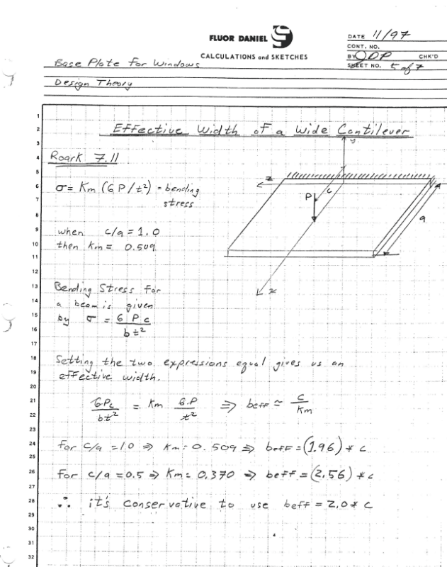
When I was at home this weekend, I found the write up I did on the Roark formula / tables used to justify the 1:1 spread.

I'm not having success uploading the file right now. My guess is there is some weird Eng-Tips issue that will get corrected on Monday. And, I'll post it then.

Summary:
Roark's Formulas for Stress and Strain, 6th Edition. Section 7.11 (title is something like "Formulas for extremely wide beams".
 
Interesting read at the link below. I make a leap of faith that it's correct. Looks reasonable anyway.

I think the use of 'effective width' in this paper is different to current use. Maybe read it as 'affected width' instead.


KootK, doesn't your method replace one estimate of effective width with another in the perpendicular direction? Or is the idea to compare both methods as a check of reasonableness?
 
Interesting articles, steveh49. The first article would need some time to evaluate but I expect it is a good prediction of the elastic behaviour of a steel or concrete plate, loaded as stated. Nowadays, engineers have FEM programs at their fingertips, so they could predict actual behaviour considerably better than the upper bound solution of the yield line method. And they would find deflection which the yield line method fails to do.

The shape of the crack patterns shown on Fig. 6 of the second article are more or less as I would expect for an application of a line load. The length of line load was 1070mm in one case and 2440mm in the other as opposed to the point load in this thread. Also, the impact factor in a crash test may introduce complications more difficult to assess than in a static test.

For static loads, yield line theory has been deemed a reasonable and relatively simple way of designing steel plates or concrete slabs. Perhaps it is time we took a more careful look at the underlying assumptions in that method. Meanwhile, increasing the load factor is a measure we are all free to take.

BA
 
I get the feeling that the real load case under discussion isn't a point load but rather distributed over a length of the cantilever plate of similar magnitude as the cantilever dimension like for the crash barrier. And the barrier test was a static load so the dynamic uncertainties aren't a factor.

I also just read another article where what looked like a straightforward yield line problem converged to the wrong solution but appeared to be optimised. The wrong solution was 40% too high (and published). Not as simple as undergraduate courses seem to suggest.
 
steveh49,

The problem here is a window mullion exerting wind force on a vertical cantilevered plate. I suppose the mullion has a width, but to all intents and purposes, it is a point load.

I would be interested in learning the source of the article you read.

BA
 
In design, I always use 1:1 (45° each side) distribution, occasionally use 35° for dealing with thrust in concrete structure. However, I believe, in reality, the peak stress occurs in a narrow bend, then gradually spread out in according to member stiffness, and conforming to its deflected shape. However, the reality has no engineering value, except in the rare event that we need to utilize the reserve capacity to justify minor over load situations.

I think the simple way to verify the distribution is to set the cantilever plate on a series of spring supports, and check the reactions corresponding to springs with varies stiffness.
 
It is a very interesting article JoshPlum provided. Quote below confirms my suspicious. The straight line failure plane, while it is not likely for the case shown in the discussion, was often assumed in old practice when dealing with column base with moment, and the bolts were placed outside of, a distance away from, the flanges.

AISC Exchange said:
A more accurate method will require further analysis. There are certainly other failure patterns that could be selected by the designer. One possible failure pattern would be a linear bend line that could form at the column flange tips. In this case, the moment arm is the distance from the bolt to the column flange tips, L (see Figure 3). Of course, at some point it would no longer make sense to increase the width of the base plate to maintain a thinner plate, so engineering judgment must be exercised.
 
Well, I got the image uploading to work again.... Finally. Here's that write up I talked about related to justifying the 1:1 spread based on a table from Roark's.

image_sjndl8.png
 
Status
Not open for further replies.

Part and Inventory Search

Sponsor