Continue to Site

Eng-Tips is the largest engineering community on the Internet

Intelligent Work Forums for Engineering Professionals

  • Congratulations cowski on being selected by the Eng-Tips community for having the most helpful posts in the forums last week. Way to Go!

Wide Cantilever Plate - Effective Bending Width? 2

Status
Not open for further replies.

AKing92

Structural
Mar 22, 2018
6
I am working on a storefront job where there is a base receptor that is basically a vertical cantilever plate, which resists the load from the mullions. I have used a rule of thumb of 1:1 for the dispersion of the load, which allows a wider plate section to be analyzed for the weak axis bending it sees. Beyond my "feeling" of 1:1, I have also worked with the AISC stair design guide, which uses a specific equation for channels. I believe that would not be valid on a cantilever plate because there is no flange to distribute the load. Any advice on an effective width for a continuous cantilever flat plate in weak axis bending?
 
Replies continue below

Recommended for you

steveh49 said:
KootK, doesn't your method replace one estimate of effective width with another in the perpendicular direction?

It does, however:

1) It's a lower bound method rather than an upper bound method which, obviously, has some curb appeal.

2) It's dirt simple to apply using methods that everyone is familiar with.
 
Yes, a lower bound method is preferable.

Unfortunately, I am not sharing JoshPlum's success in image uploading. Am I alone?

BA
 
BARetired -

You're not alone. The Eng-Tips moderators / developers are looking at it. FWIW, I was able to get it to work by resetting my browser, deleting cookies, browser settings, loading latest version of browser and resetting to default settings. No idea what caused it and why so many others have the same problem at the same time.
 
Thanks Josh. I'm glad to hear I am not alone, but I think I will wait for the developers to fix the problem as my reputation for fixing anything to do with computers is not exactly sterling.

BA
 
This doesn't really contribute intellectually to the discussion, but I think it's good to consider the approach AISC recommends for prying action. It's a similar scenario - point load applied to a cantilevered plate is a lot like a point load applied to a flange cantilevered from a beam web. The angle used to define "p" (the tributary length) is 45o and p is capped at 2b, where b is the distance from the bolt hole (point load) to the rigidly supported edge of the flange (plate).
 
phamENG, the AISC recommendations for prying action have been updated in the latest edition and provide the guidance to conservatively use 3.5b due to more recent research (Dowswell 2011 and Wheeler et al 1998).

I believe this is actually a different application because with prying action, the plate bends in double curvature (essentially fixed at the stem/application of load and at the bolt line). With the situation discussed here, the plate is free to rotate at the point of load application and can therefore bend in single curvature. Hopefully I'm being clear, I have attached the figure from AISC showing what I mean about the double curvature.

prying_jo9lyk.png
 
Thanks, dauwerda. I was unaware of the update (my states are still using the 2015IBC and 360-10, so I haven't updated my library yet). Solid point on the double curvature - I didn't mean to suggest the calculation method should be applied here. I was merely commenting on the fact that they used 45 degrees to look at the effective length of the flange contributing to the resistance of the point load. Though if they've increased the max for p to 3.5b, that means they're now looking at 56 degrees. Interesting.

Looking at JoshPlumSE's old hand calc above and thinking about the double curvature, maybe that's why they found it goes out to 3.5b. Pin-fixed will be around 2 or greater, but fixed-fixed will be 3.5 or greater.
 
Wow, I am pleased to see that image uploading works again!!!

BA
 
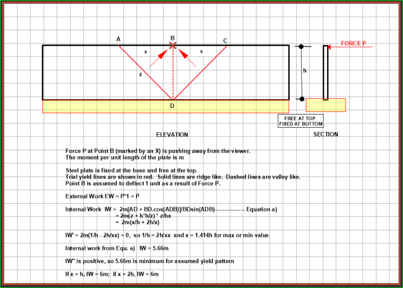
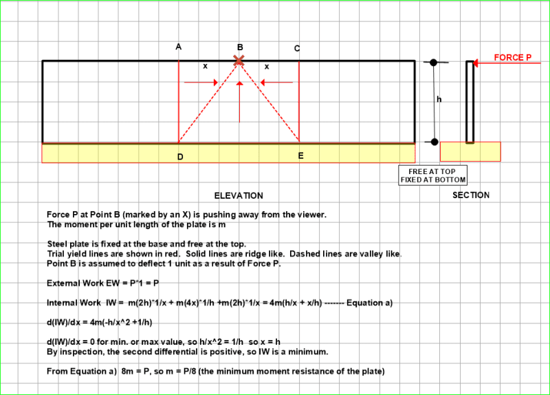
Now that we can include graphics, the following are the two Yield Line patterns which I considered:

The first one I believe is the simplest and best choice, but both patterns confirm that the 1:1 ratio is conservative. The 'x' dimension is 1.414h and h for the first and second patterns. Both are of course upper bound solutions and as others have said, are not as acceptable as lower bound solutions. The Hillerborg strip method is a lower bound solution and would be perhaps a better choice for the analysis.

CantileveredSteelPlate002_hzt71k.png


CantileveredSteelPlate_qkgkaz.png


BA
 
Status
Not open for further replies.

Part and Inventory Search

Sponsor