Eng-Tips is the largest engineering community on the Internet

Intelligent Work Forums for Engineering Professionals

Width variation of a feature

Status
Not open for further replies.

Burunduk

Mechanical
May 2, 2019
2,335
0
0
IL
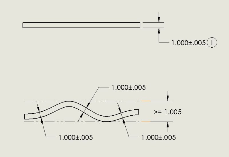
Please consider a design intent where the variation on the width of a feature of size is more important than the measured value itself. For example, a part feature needs to be of width 4.1mm Max and 3.9mm Min, but the variation on that feature width can only be within 0.07. For example, if the width along the actual produced feature varies between 4.03 and 4.1 the part is acceptable. But If the width varies between 3.95 and 4.05 the part should be rejected as the variation is within 0.1 which is more than 0.07.

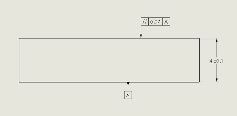
How would you specify this requirement in accordance with ASME Y14.5 (any revision year)? Would you attempt to achieve this requirement by a geometrical control or combination of controls (size and parallelism? Some sort of profile? Size and form tolerances? Size and runout tolerances?) Or would you specify 4+-0.1 and write a custom note describing the variation requirement?
 
Replies continue below

Recommended for you

chez311 said:
CH/drawoh,
That doesn't really sound like parallelism as parallelism would certainly control form within the desired range. OP has said they desire no control over form besides what rule #1 will provide.

I would think that "variation in width" is a good definition of parallelism, albeit, not a perfect one.

--
JHG
 
Drawoh,

It's actually variation in size which is sought - a slight but important distinction. I can imagine extreme form deviations that would be allowed with OP's stated desire to control size variation that would be restricted (not allowed) with a parallelism tolerance of the same range.

That is to say, parallelism certainly limits size variation, but also limits form deviation - which OP expressly stated was not desired.
 
I was very intrigued when I first saw that use of parallelism in the ISO. I thought it would be perfect for an issue I was dealing with very similar to the issue CH had showed as the acceptable version,above. When I finally had a chance to study the ISO based books on this I realized it was intended, not as I desired but, was invoking a type of reciprocity where either is the datum for the other. Invoking a datum (the image of perfection) is what ruins it in this case. I think note is all you have.
Frank
 
If the min/max values of the envelope not matter due to deformation/waviness but the material thickness should be constrained then it may be a case where you want to invoke independence:

Independence_qwajvn.jpg
 
Th.Ro.

See below quote from OP. I suggested as such previously, it seems rule #1 envelope control of form is desired.

It's not really a part that is subjected to free form variation to the point that rule #1 can be dismissed, but it is not a very rigid part either. Right now they just want two-point measurements for checking both the limits of size and "size variation" along the feature. In addition, I'm going to push for rule #1 control
 
If the thickness tolerance for all parts is larger than the allowable variation within one part then maybe something like this could work:

Example_3_bcgnwq.jpg
 
Th. Ro.
The situation is that width variation along a feature (not between different parts) must be smaller than the size tolerance of that same feature.
 

PS2. In ISO GPS/GD&T language there is a standardized modifier that would pretty nicely grasp the design intent without a need to use a descriptive note. It is SR modifier enclosed within an oval that follows a numerical value defining the maximum allowable difference (range) between max and min values of local (two-point) size measurements. For more details see ISO 14405-1:2010.


Credit to pmarc
 
Status
Not open for further replies.
Back
Top