Continue to Site

Eng-Tips is the largest engineering community on the Internet

Intelligent Work Forums for Engineering Professionals

  • Congratulations MintJulep on being selected by the Eng-Tips community for having the most helpful posts in the forums last week. Way to Go!

Wind Blade Design - "Through face does not intersect path of the tool" 2

Status
Not open for further replies.

DanielatVT

Mechanical
Jan 21, 2016
6
Hi All,

I am a graduate research assistant at Virginia Tech with 2 year NX experience. I have built a wind blade using swept and then sew the surface with bounded planes to create a solid body.

When I tried to unite the hub and the blade, a error message "Through face does not intersect path of the tool" showed up. I am not sure what is causing it since two body are intersected.

If there is solution to there issue or better ways to build a wind blade into solid body, please let me know. I really appreciate it.

I have attach the file in the below link. The curve is on layer 5.


Thanks!
 
Replies continue below

Recommended for you

When boolean operations do not work when they apparanetly should, the first thing to do is run "examine geometry" on the bodies and faces. Your blade solid has both body consistency and face self-intersection errors. When these are fixed, the unite will work.

www.nxjournaling.com
 
Yes, that was my first observation as well and since ALL of the 'problems' were pointing toward the solid body representing the airfoil, I looked at how it was constructed and while the profile curves looked OK so I decided it must be the method you used to create the airfoil surface itself. I therefore used a 'Surface Through Curves' instead and then used a 'Shell' operation to get the hollow body. Then there was no problem getting the tho resulting solid bodies to Unite. I've attached my effort below. Note that it passes all the 'Examine Geometry' tests that one would expect it to pass. I also left your old airfoil in the model but its features are currently suppressed.

John R. Baker, P.E.
Product 'Evangelist'
Product Engineering Software
Siemens PLM Software Inc.
Digital Factory
Cypress, CA
Siemens PLM:
UG/NX Museum:

To an Engineer, the glass is twice as big as it needs to be.
 
 http://files.engineering.com/getfile.aspx?folder=c696741d-3384-4cd6-8be8-03ead8fbba74&file=Airfoil_1-JRB-1.prt
Hi All,

I want to thank you for all your reply. It helps me a lot learning NX.

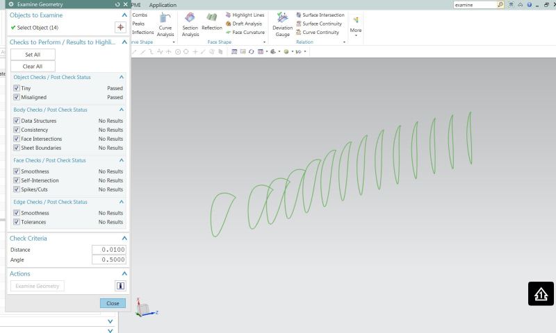
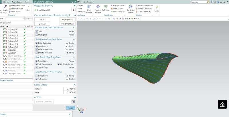
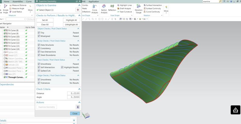
I have examined my curves and solid bodies built by two different features (Through Cruve/Swept)
The curves has no self-intersect error, but both two solid bodies has this issue.

I will see where I did wrong compared to John's model.

Curve_Examine_njltaw.jpg

Swept_Examine_vd0jd1.jpg

Through_Curve_Examine_undu0j.jpg
 
Did you look at my 'Surface Through Curves' resulting Solid Body? It passed all the tests except 'Smoothness' but that's just telling you that there are hard corners, but that's to be expected.

John R. Baker, P.E.
Product 'Evangelist'
Product Engineering Software
Siemens PLM Software Inc.
Digital Factory
Cypress, CA
Siemens PLM:
UG/NX Museum:

To an Engineer, the glass is twice as big as it needs to be.
 
Hi John,

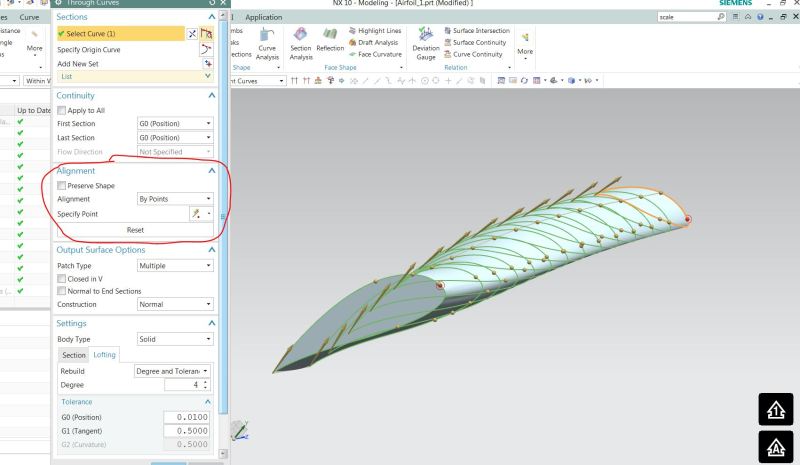
I believe I used wrong Alignment options in Through Curve feature. I used "parameter" option and the result has self-intersect error. If I switch to "By point" option, the result is perfect solid with no error.

Blade_Model_fjinls.jpg


Again, thank you for your help.
 
I do not agree on that the construction is ok.

I hope you take the following as constructive critic and not negative.

1) The model size ? The cylinder in the center is 3 millimeter in diameter !?!
I can understand the size if this is a fan, but a wind blade ? Or are you modeling is scale 1:something ?

2) all these sections, having this many sections for this shape tends to "overload" the resulting surfaces. You simply cannot have input data which is accurate enough to produce smooth surfaces.

3) The sections themselves, You have used a fitting tolerance of 0.0001 millimeters. This is very tight, and i assume that you have fitted this to something which came out of a CFD simulation ?
In the CFD simulation the accuracy was what ? ( i doubt that it was lower than 0.0001, rather say 0.1mm! CFD systems are not designed for extreme accuracy, rather to crunch enormous amounts of data. Plus they do it on elements which are either linear or "cubic".)
Have you looked at a curvature comb of one of the sections ? The sections are far from smooth. Turn ON the curvature comb when you do the fit splines and you will see the result of this extreme tolerance.
Zoom in on these sections, Update the display and you can see the undulations in the sections. In the image i have highlighted one section with curvature comb and one section without comb. The periphery of the comb exaggerates/ illustrates the undulations.
See attached image.

The resulting face, there is only one face, has a G0 ( position) tolerance of 0.01 mm to the input curves, which actually will smooth out some of the undulations in the sections.
If you would use the same tolerance on the sheet to the sections, it will be rather ugly.

I agree on the method John proposed, a Surface through curves is a simpler and better method.

Suppress the surfaces. Go back and edit each section such that you get a balance between shape ( look at the curvature comb) and tolerance to the input data. Try to have a consistent number of segments in the splines, the surface will be simpler ( (less data )smoother and by far faster to work with. Subsequent features such as Unite, shell/ offset, blending etc will work without trouble, updates etc will work .
See if you can skip every other section but keep the shape / position.

The surface can never be better than the input curves.

Regards,
Tomas


 http://files.engineering.com/getfile.aspx?folder=47e2b5bd-2062-4b82-9835-58b76b94ad7b&file=wind_blade_sections.png
Here's an example of the above.
I edited the sections and applied a fitting tolerance of 0.01mm, this renders a very nice looking curvature comb where one sees the expected shape of the section.
The splines have a max deviation to the definition points of ~0.008mm ( Edit one of the sections ,the deviation is noted in the bottom of the dialog.)
- The size of the deviation is in this case difficult to judge whether it's reasonable or not, since the overall size is so small.

I then re-created the Surface through curves but using only every other section. The Surface uses the default tolerance of 0.01.
Depending on the settings in the dialog, NX will create a solid body instead of Sheet body. The settings i used created a solid body. One can probably play with the settings in the
surface dialog to get a even simpler surface output.

You can check which sections are used by the surface, and do a deviation check to the sections which aren't used.
There will be a deviation but again, if it's ok or not is difficult to decide.

This body can be united to the cylinder without hesitation.
I also applied a blend just to see if it works.
If this blend works / allows a rather large size, it's a sign that the surface is smooth.

Regards,
Tomas
 
 http://files.engineering.com/getfile.aspx?folder=1799bef6-5d7d-418d-82c1-0ece77029837&file=Airfoil_1-tomas-1.prt
Here's an example / explanation of what i mean when i say "Overloaded" surface or curve.
Suppose you feed NX with point data from "somewhere else".
Suppose this point data should produce a line (note the type here) in space. I get 23 points from that other system.
I, the cad jockey, don't know that the result should be a line, so when i see 23 points, i will create a spline from these.
It's very difficult to have absolutely exact data, which i hope that this example will highlight, and the more of the almost exact data there is, the worse it gets.

In the example i have drawn a line ~159 mm long, diagonally XYZ.
I then created a "point set" , 23 points equally spaced, non-associative on the line. ( these are exact within NX system tolerance which is very tight.)
I then moved a few of the points, away from the line, i think the point which has the maximum deviation to the line is off 0.002 mm. ( I might have moved that one twice...)

If I , using these points, create a "Studio spline", the spline will undulate ( waves) since it passes all points and some of the points are slightly slightly off.
The fewer of the 23 points i use, the smoother ( less undulations ) the spline will be, and in the end if i only select the end points, the spline will be linear.
This method is pretty tricky to do , and it will be more difficult if the resulting shape is complex.

The easier method is to use a fit spline, and there allow some deviation from the "off points" and at the same time return a nice shape.
The simplest way to determine the shape is to use the curvature comb because the comb will exaggerate and show the undulations/ the shape.
The curvature comb is "Curvature"= 1/r * Scalefactor. Where "r" is "radius of spline at this position" and the result is : If "r" is small, a long corresponding line will be displayed, if "r" is large a short corresponding line will be displayed.

Look at the spline in the attached part ( NX10), try to see any errors ( waviness). Then press Ctrl+Shift+ U to un-hide the curvature comb.
This curve is "overloaded" with data, it contains way more data than needed for the shape. It uses all 23 points and the result is "undulations" / Waviness/ non-smoothness.
With the comb still displayed, edit the "Fit spline", note the deviation. Edit/ increase the tolerance . (at tolerance 0.002 the the comb will disappear indicating that it's pretty straight.)
There will be a marker displayed where the largest deviation is.

This behavior is of course the same in both splines and Surfaces, but in surfaces it occurs in both U and V direction.

Regards,
Tomas


 http://files.engineering.com/getfile.aspx?folder=1ba7a250-cc88-4b70-8d5d-38264ad8d420&file=overloaded_spline.prt
Status
Not open for further replies.

Part and Inventory Search

Sponsor