Continue to Site

Eng-Tips is the largest engineering community on the Internet

Intelligent Work Forums for Engineering Professionals

  • Congratulations KootK on being selected by the Eng-Tips community for having the most helpful posts in the forums last week. Way to Go!

Wind force coefficient in open frame model

Apr 29, 2023
31
Wind force coefficients for flat sided individual members are dependent on their slenderness (and thus their length as seen in design codes like British standards, Eurocodes , DNV , etc). It's easy to incorporate that for single member and there's guidelines for doing so with a regular lattice frame. It's more awkward to assign individual wind force coefficient values by hand (based on length, orientation and height from ground) to every single member when the number of members increases significantly. That approach really requires using software with such a capacity.

My question is what is your approach for assigning wind force coefficients for flat sided members in a non regular non lattice unclad open frame with a significant amount of members, either in hand calcs or FEA models.

Do you just take the conservative infinite length value (ignoring end effects reductions due to length) of approx 2.0 ?

Do you try to rationalize an average length of all members in your structure?

Do you assume a unit length of 1.0 m (as with other loads/resistances etc) ?

Do you treat the non regular frame as regular enough for your purposes and use the lattice frame overall coefficient based on solidity ?

or have an approach not mentioned?


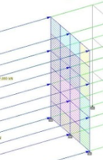
Example structure could be similar to the following image (not mine)
 

Attachments

  • 1729934205026.png
    1729934205026.png
    154.4 KB · Views: 20
Replies continue below

Recommended for you

I use GTSTRUDL which has a ASCE 7 wind loading module that would handle this open frame. There may be other programs that do something like this. IIRC, they have a free demo version. If you know some other FEA program, the learning curve may not be too bad. I've used GTS for 40 years.
 
It would really be helpful to have a hand sketch or other image with the relevant items labeled for this discussion.
 
The image attached in the first message hopefully coveys the concept of a non regular lattice unclad open frame with a significant amount of members.

Approach 1 uses infinite length coefficients, sketching an infinite beam might be hard.

Approach 2 suggests using average length, sketch is > for beams --- and - long, the average length to be used with the coeff is --

Approach 3 suggests normalization of length based on unit lengths. Sketch for a 1 unit long beam is > -

Approach 4 suggests a value based on overall frame solidarity like so a 0-1.0 value based on this area:

1730309285165.png


What relevant items require a labelled sketch? It would be really helpful to know what info you require.
 
I use GTSTRUDL which has a ASCE 7 wind loading module that would handle this open frame. There may be other programs that do something like this. IIRC, they have a free demo version. If you know some other FEA program, the learning curve may not be too bad. I've used GTS for 40 years.

Thanks for the recommendation. I had a look for any theory docs for the software that might explain their approach in detail but was unsuccessful.
 
I generally just use a shape factor of 2 for everything with no shielding and call it a day. If it governs on something by a lot I might come back to it, but it's not normally worth the effort.

It makes application and checking significantly more straightforward.
 
Thanks for the recommendation. I had a look for any theory docs for the software that might explain their approach in detail but was unsuccessful.
GTSTRUDL is maintained by a bunch of PhD structural engineers and when they implement something like ASCE 7, they go into the utmost trivia. You can be sure they used every equation in ASCE 7 for complete coverage.

Like someone else said, use a shape factor of 2 on all members and do some spot checks to see what the loads are. 😉
 
Appreciate the responses folks, the consensus forming seems to be to simply take the conservative infinite length coefficient of 2.0 when considering individual elements.

GTSTRUDL is maintained by a bunch of PhD structural engineers and when they implement something like ASCE 7, they go into the utmost trivia. You can be sure they used every equation in ASCE 7 for complete coverage.

Like someone else said, use a shape factor of 2 on all members and do some spot checks to see what the loads are. 😉

Not familiar with ASCE 7 but from a quick scroll through it , I couldnt find any information on wind coefficients for individual elements. It seems that ASCE 7 takes the overall area solidity approach with different coeff based on solidity, overall structural aspect ratio and shape, and element type, (assuming i read figure 29.5 correctly).

So that ASCE 7 approach might be less conservative than the infinite length 2.0 value but i'm not sure how much leeway there is to use those values .


The topic comes up because of tall, lightweight, narrow structures that result in increased foundation sizes due to overturning by wind load ,so taking the easy conservative value ends up driving the final design with significant foundations relative to the rest of the structure.
 
One of the primary references for this topic is Wind Load Design for Petrochemical and Other Industrial Facilities.

A lot of the stuff, and it's companion earthquake volume, has been incorporated into the primary body of ASCE-7 at this point, but it's still a better treatment.


Part and Inventory Search

Sponsor